EasyManuals Logo

Suzuki DF 40 User Manual

Suzuki DF 40
405 pages
To Next Page IconTo Next Page
To Previous Page IconTo Previous Page
Page #131 background imageLoading...
Page #131 background image
5-7 FUEL SYSTEM
REMOVAL / INSTALLATION
Removal
A
The components after the high pressure fuel pump re-
main pressurized at all times.
To protect against fuel spray, relieve fuel line pressure
before disconnecting or removing components.
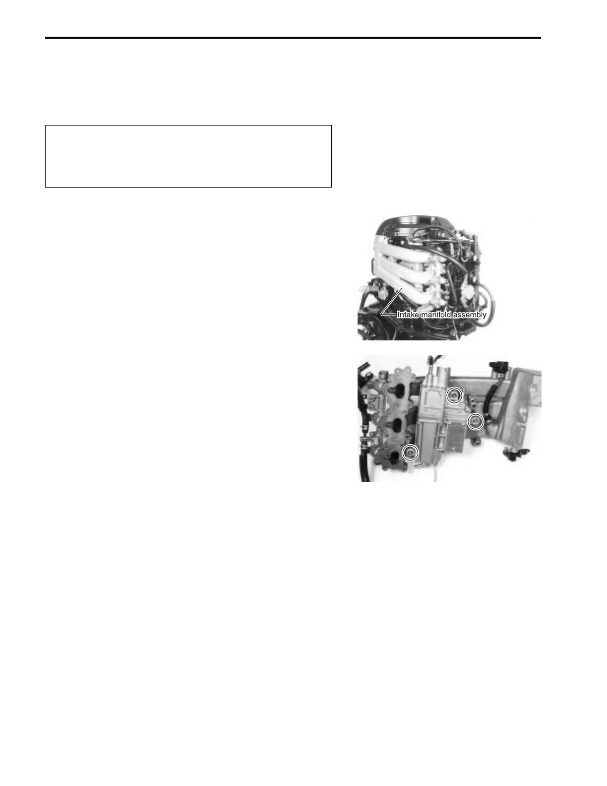
• Remove intake manifold assembly.
(See page 6-1)
• Remove three bolts and fuel vapor separator assembly from
intake manifold.
Installation
Installation is reverse order of removal.
See page 6-2 for installation of intake manifold assembly.
FUEL VAPOR SEPARATOR / HIGH PRESSURE FUEL PUMP

Table of Contents

Other manuals for Suzuki DF 40

Questions and Answers:

Question and Answer IconNeed help?

Do you have a question about the Suzuki DF 40 and is the answer not in the manual?

Suzuki DF 40 Specifications

General IconGeneral
Displacement941 cc
Starting SystemElectric
No. of Cylinders3
SteeringRemote
Gear Ratio2.27:1
Alternator Output12V 19A
Engine Type4-Stroke, DOHC
Maximum Output40 hp
Fuel SystemMulti-Point Sequential Electronic Fuel Injection
Shaft LengthS: 381 mm, L: 508 mm
Oil Capacity2.7 L

Related product manuals