12 DF40/50
"K5"
('05)
MODEL
PTTMOTOR
Brush
length STD
mm
(in)
9.8 (0.39)
Limit
mm
(in)
4.8 (0.19)
Commutator outside
I STD I
mm
(in)
22.0 (0.87)
diameter
Limit
I
mm
(in)
21.0 (0.83)
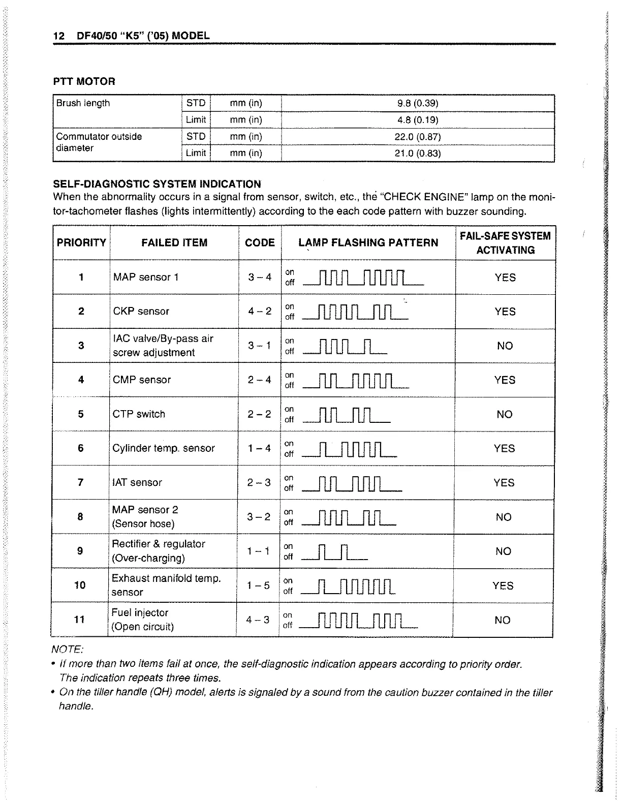
SELF-DIAGNOSTIC
SYSTEM
INDICATION
When the abnormality occurs in a signal from sensor, switch, etc., the "CHECK ENGINE" lamp on the moni-
tor-tachometer flashes
(lights intermittently) according to the each code pattern with buzzer sounding.
i
,
FAIL-SAFE
SYSTEM
PRIORITY FAILED ITEM
CODE
i
LAMP FLASHING PATTERN
ACTIVATING
1 MAP sensor 1
3-4
on
~
YES
I
off
2 CKP sensor
4-2
on
~
YES
off
3
lAC valve/By-pass air
I
3-1
on
-.llJlJLJL
I
NO
I
off
,
screw adjustment
i
4 I CMP sensor
2-4
on
~
YES
,
off
5 CTP switch
I
2-2
on
~
NO
off
-------
6 Cylinder temp. sensor
1-4
on
~
,
YES
off
,
i
I
7 IAT sensor
2-3
on
--.-flJLJlJ1JL
YES
off
8
. MAP sensor 2
3-2
on
~
NO
(Sensor hose)
off
Rectifier & regulator
I
9
1 - 1
on
~
NO
i (Over-charging)
off
:
10
Exhaust manifold temp.
1 - 5
Ion
~
YES
sensor
I
off
11
Fuel injector
I
4-3
Ion
~f1J1JUlJlJL
NO
I (Open circuit)
I
I
off
L.
NOTE:
•
If
more than two items fail
at
once, the self-diagnostic indication appears according to priority order.
The indication repeats three times .
• On the tiller handle (QH) model, alerts is signaled
by
a sound from the caution buzzer contained in the tiller
handle.
 Loading...


