40 DF40/50
"K5"
('05) MODEL
In
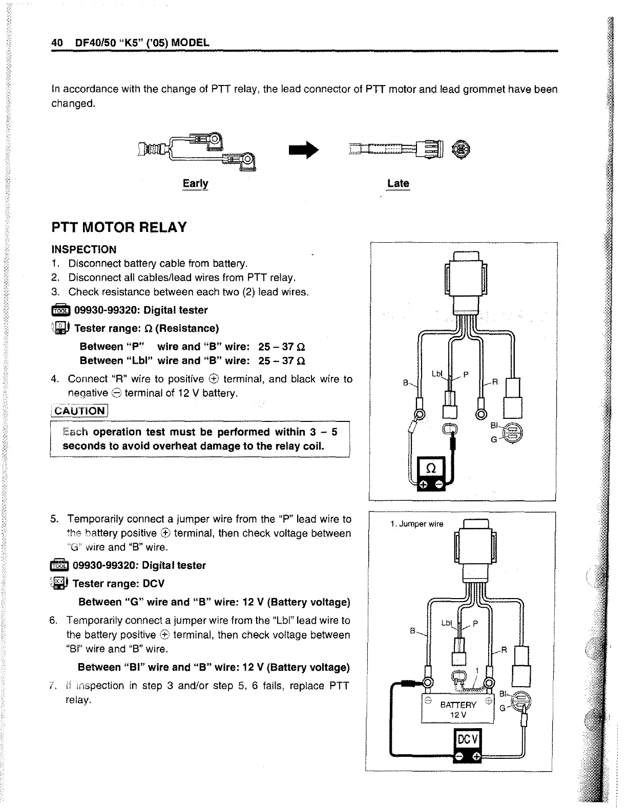
accordance with the change of PTT relay, the lead connector
of
PTT motor and lead grommet have been
changed.
..
PTT MOTOR RELAY
INSPECTION
1.
Disconnect battery cable
from
battery.
2.
Disconnect all cables/lead wires from PTT relay.
3.
Check resistance between each two
(2)
lead wires.
51 09930-99320: Digital tester
~
Tester range: 0 (Resistance)
Between
"P"
wire
and
"B"
wire: 25 -
37
0
Between
"Lbl"
wire
and
"B"
wire:
25
- 37 0
4.
Connect
"R"
wire
to
positive e terminal, and black wire to
negative
8 terminal of
12
V battery .
•
CAlJTIOJij
Each operation
test
must
be performed
within
3 - 5
seconds
to
avoid overheat damage
to
the relay coil.
5.
Temporarily connect a jumper wire from the "P" lead wire to
the battery positive e terminal, then check voltage between
"'Gl'
wire
and
1'8"
wire.
IrULI
09930-99320: Digital tester
:i!lJ
Tester range:
DCV
Between
"G"
wire and
"B"
wire: 12 V (Battery voltage)
6.
Temporarily connect a jumper wire from the "Lbl" lead wire to
the battery positive
'3::
terminal, then check voltage between
"81"
wire and "8" wire.
Between
"BI"
wire and
"B"
wire: 12 V (Battery voltage)
1.
Ij
inspection
in
step 3 and/or step
5,
6 fails, replace PTT
relay.
Late
p
1. Jumper wire
B
,
Lbl
p
R
o
8
BATTERY
ffi
:Ir
12V
!J