3-37 ENGINE CONTROL SYSTEM
FUEL PUMP 3 SEC. OPERATING SOUND
Turn ignition switch ON and check for fuel pump operating
sound.
Fuel pump operating sound :
Sounds for approx. 3 seconds only
NOTE:
Fuel pump operating sound is low because pump is in fuel va-
por separator. If you cannot hear clearly, use a sound scope or
long blade screw driver.
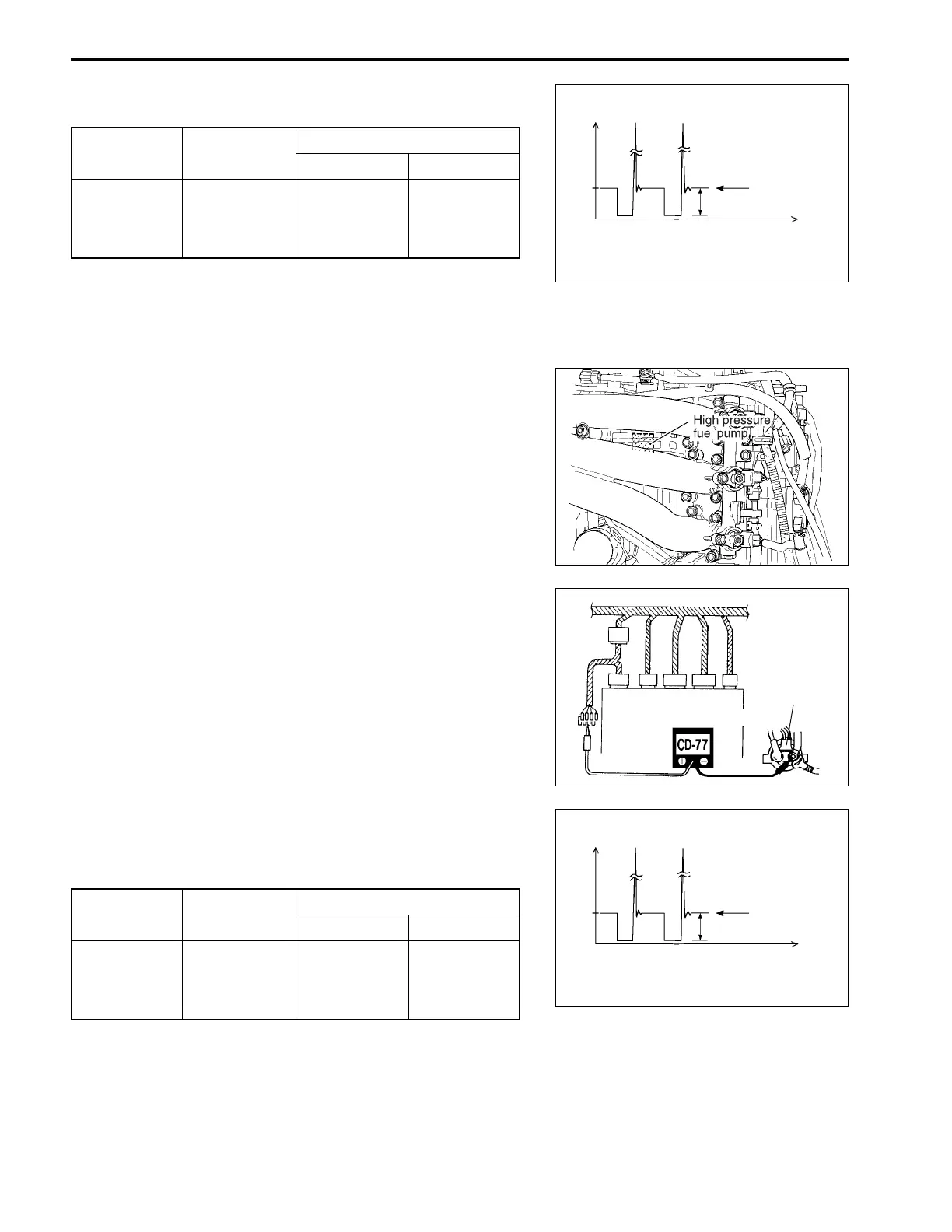
IGNITION COIL OPERATING SIGNAL
09930-89930 : 8-pin test cord
Peak voltmeter Stevens CD-77
Tester range : NEG50
(1) Connect the test cords as shown, then turn ignition switch
ON.
(2) Connect the tester probe - (Black) to starter motor relay
right terminal (connected to battery positive (+) terminal)
as shown.
(3) Connect the tester probe + (Red) to each terminal.
Ignition coil Terminal
Engine
Wire color
Test cord
No.1 A5 O O
No.2 A1 Bl Bl
No.3 A3 G B/W
(4) Crank engine and measure voltage.
Ignition coil operating signal : 6 – 10 V
Injector Terminal
Engine
Wire color
Test cord
No.1 A4 O/B B/R
No.2 A7 B/Y B/Y
No.3 A8 R/W Lg
(4) Crank engine and measure voltage.
Fuel injector operating signal : 6 – 10 V
(Voltage)
12V
(Time)
A
B
A Peak voltage reading (NEG)
B 0V level for peak voltmeter
Starter
motor
relay
ECM
E
D
C
B
A
(Voltage)
12V
(Time)
A
B
A Peak voltage reading (NEG)
B 0V level for peak voltmeter
(3) Connect the tester probe + (Red) to each terminal.
z
q