4-10 ELECTRICAL
Be careful not to touch 12V power supply wires to each
other or with other terminals.
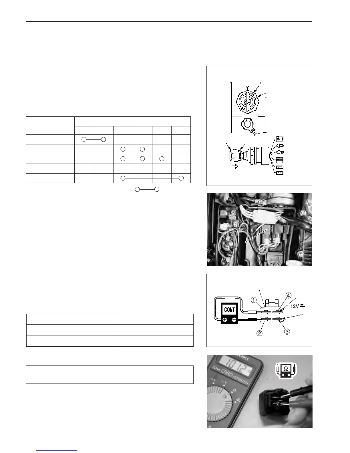
INSPECTION
IGNITION SWITCH
\ 09930-99320 : Digital tester
T Tester range : @ (Continuity)
1. Disconnect ignition switch from remo-con box wiring har-
ness.
2. Inspect continuity between wiring leads at key positions
shown in chart.
If out of specification, replace ignition switch.
Key
Position
1 OFF
Switch Lead Wires
Black
Green White Gray Brown
Orange
2 ON
3 START
4 FREE
5 PUSH
: Continuity
Black
Green
White
Gray
Orange
Brown
1 (OFF)
2 (ON)
3 (START)
4 (FREE)
5 (PUSH)
PUSH
STARTER MOTOR RELAY
\ 09930-99320 : Digital tester
T Tester range :
@@
@@
@ (Continuity)
1. Disconnect starter motor relay from wire.
2. Inspect continuity between terminal 1 and 2 each time 12V
is applied. Connect positive + side to terminal 4, and nega-
tive - side to terminal 3.
Applied
Not applied
Ye s
No
12V power
Continuity
Starter motor relay function :
3. Measure resistance between relay terminals 3 and 4.
V Tester range :
ΩΩ
ΩΩ
Ω (Resistance)
Starter motor relay solenoid coil resistance : 80–120
ΩΩ
ΩΩ
Ω
If out of specification, replace starter motor relay.
11
1. Starter motor relay
Starter motor relay