POWER UNIT 6-17
INSTALLATION
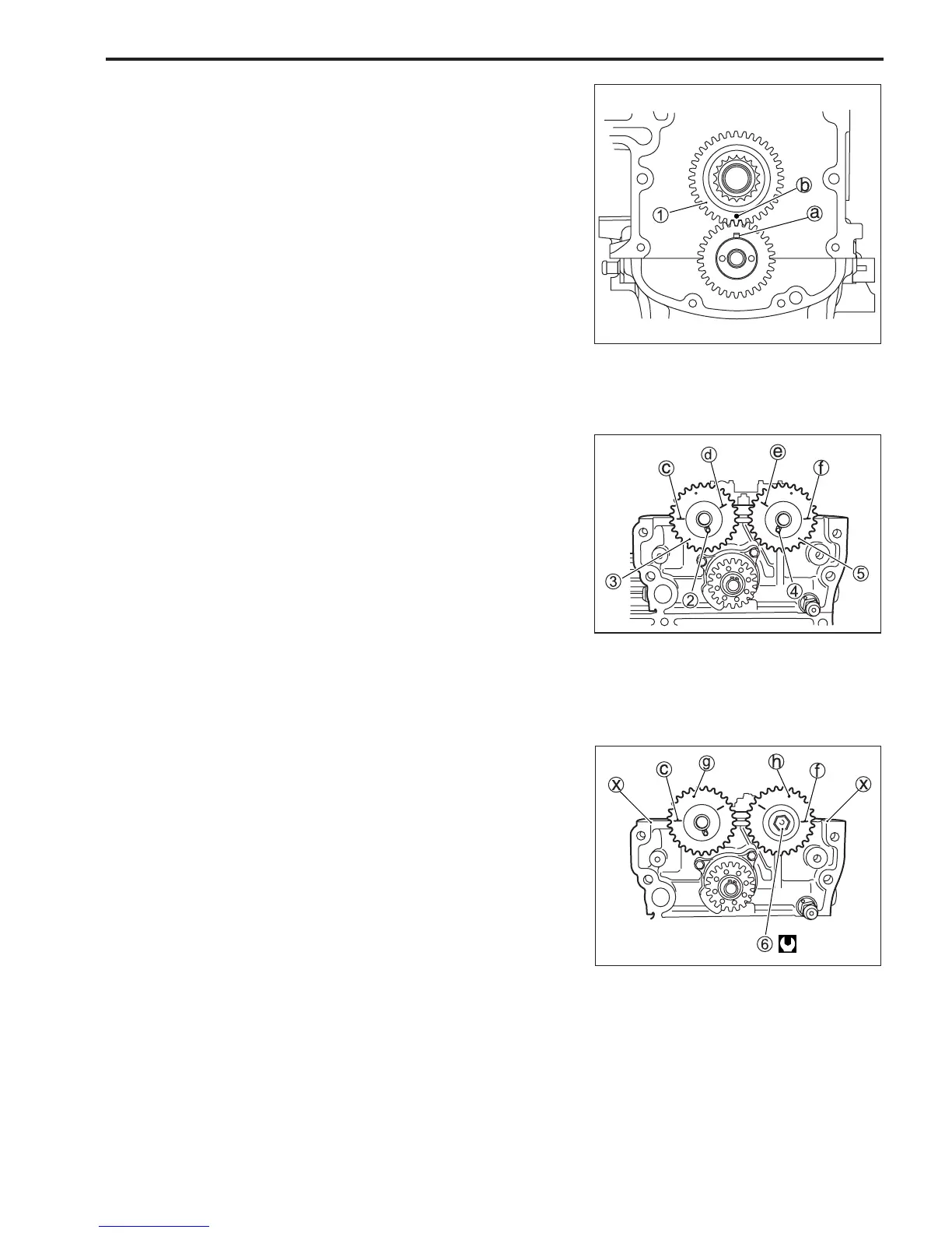
Installation is reverse order of removal with special attention to
the following steps.
1. Check that match mark (key way) a on crankshaft drive
gear points to 12 o’clock (towards cylinder head).
(Check that #1 cylinder is at top dead center.)
2. Install driven gear 1 on cylinder block so that match mark
(key way) a aligns with match mark ( • ) b on driven gear
as shown in figure.
3. Install dowel pin 2 and sprocket 3 on exhaust camshaft.
Install dowel pin 4 and sprocket 5 on intake camshaft,
then tighten bolt 6 securely.
" Timing sprocket bolt : 78 N
.
m (7.8 kg-m, 56.5 lb.-ft.)
NOTE:
When installing camshaft sprocket, position side of sprocket
with two engraved lines
c,d,e and f
facing down toward
engine holder as shown in figure.
4. Check that engraved lines c and f on sprockets are
opposite each other and aligned with mating face x
of
cylinder head cover when match marks (dot) g and h on
sprockets are located as shown in figure.