FUEL SYSTEM 5-5
1
2
3
1. High pressure fuel filter
2. Fuel delivery pipe
3. Delivery pipe upper plug
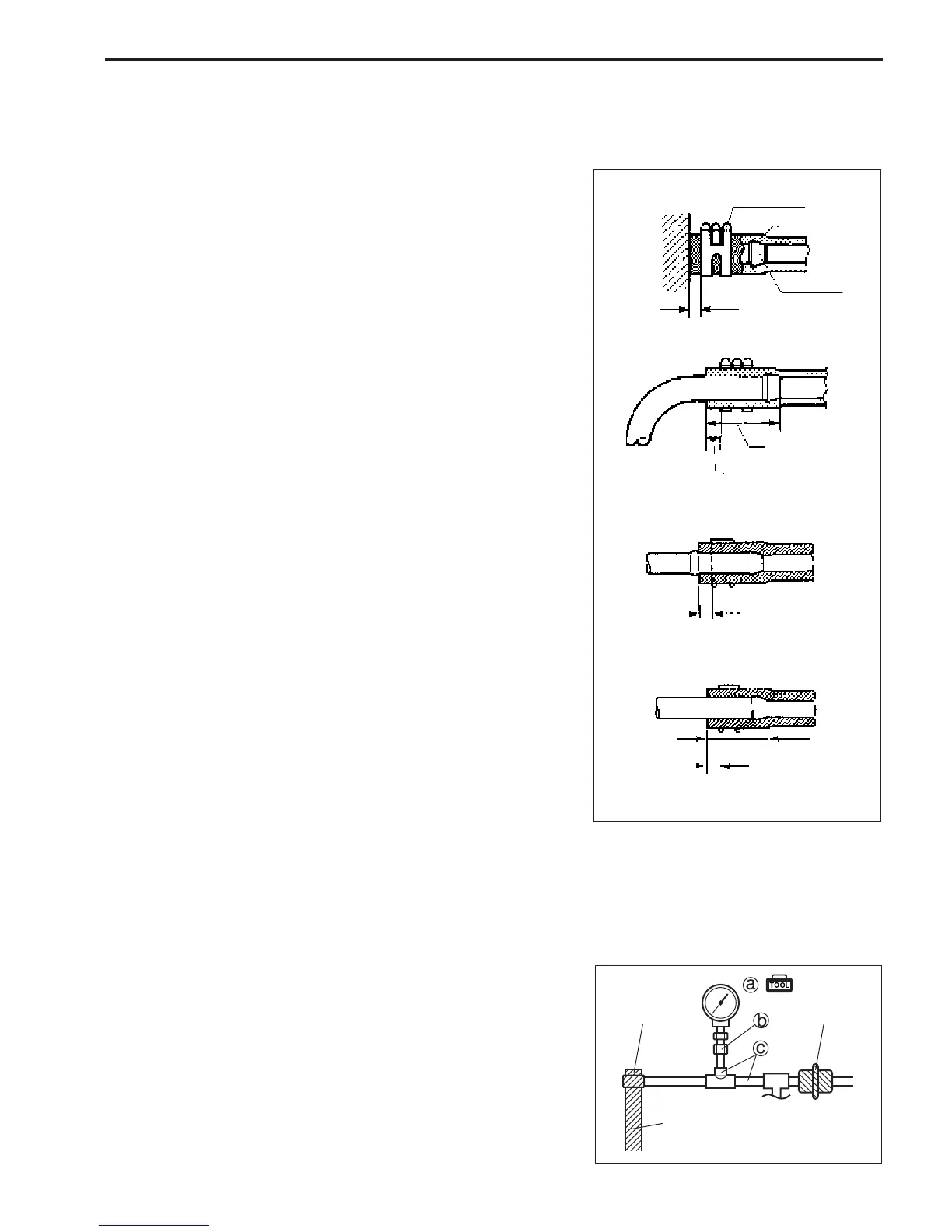
FUEL HOSE CONNECTION
Note that fuel hose connection varies with each type of pipe. Be
sure to connect and clamp each hose correctly by referring to
following figures.
• For type “A” (short barbed end) pipe, hose should completely
cover pipe.
Clamp (Clip)
Hose
Joint pipe
3 – 7 mm
(0.1 – 0.3 in)
3 – 7 mm
(0.1 – 0.3 in.)
20 – 30 mm
(0.8 – 1.2 in.)
3 – 7 mm (0.1 – 0.3 in.)
3 – 7 mm
(0.1 – 0.3 in.)
20 – 30 mm
(0.8 – 1.2 in.)
• For type “B” (bent end) pipe, hose should cover straight part
of pipe by 20 – 30mm (0.8 – 1.2 in.).
• For type “C” pipe, hose should fit up against flanged part of
pipe.
• For type “D” pipe, hose should cover pipe by 20 – 30 mm (0.8
– 1.2 in.).
“A”
“B”
“C”
“D”
FUEL PRESSURE INSPECTION
1. Relieve fuel pressure in fuel feed line. (See page 5-3.)
2. Loosen delivery pipe upper plug.
3. Connect special tools (pressure gauge, pressure hose &
pressure joint) between fuel feed hose and delivery pipe as
shown in figure.
Tighten delivery pipe upper plug to specified torque.
Clamp hose securely to ensure no leaks occur during check-
ing.
\ 09912-58442 : Pressure gauge –
aa
aa
a
09912-58432 : Fuel pressure hose –
bb
bb
b
09912-58490 : Fuel pressure joint –
cc
cc
c

 Loading...


