3-2 ENGINE CONTROL SYSTEM
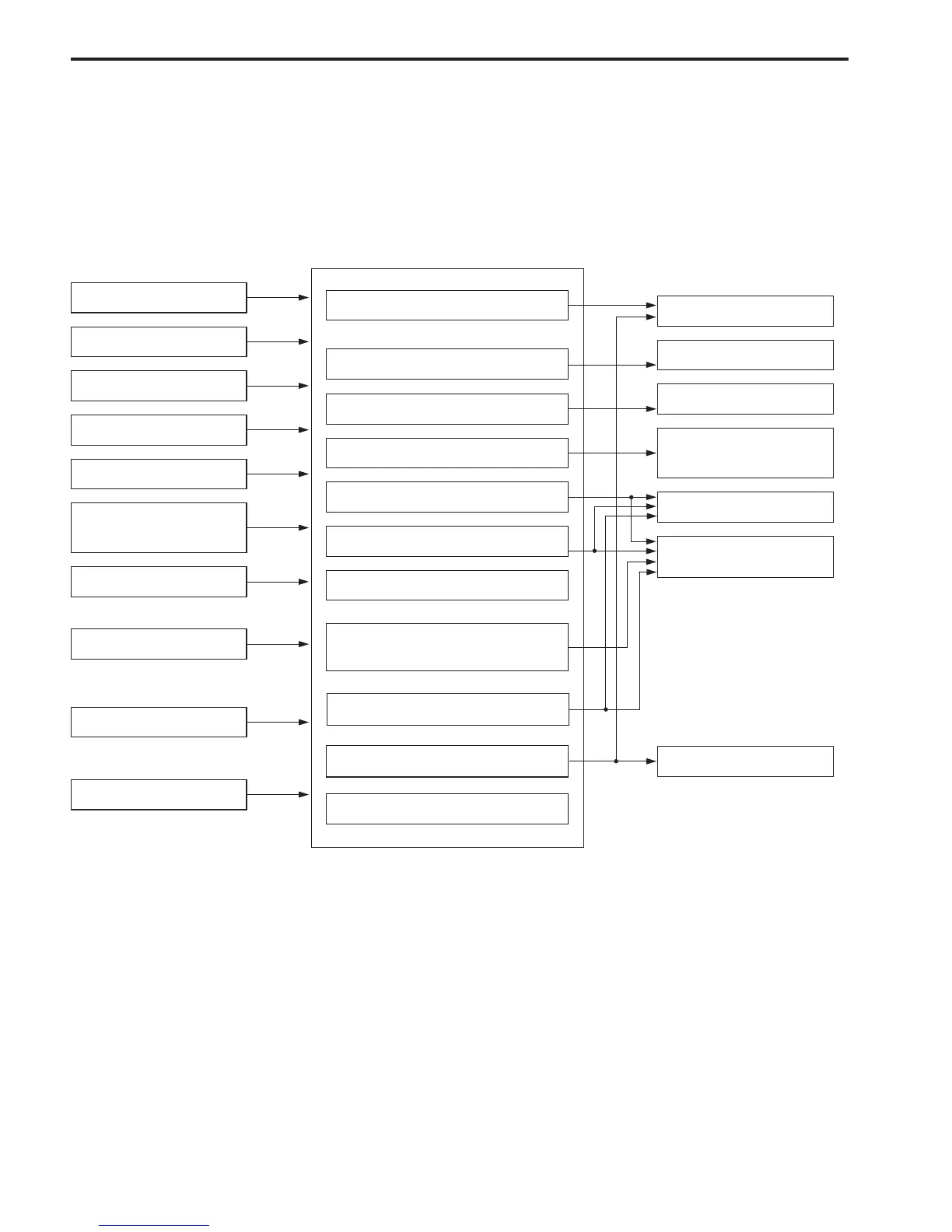
ENGINE CONTROL SYSTEM STRUCTURE
The DF90/DF115 models employ an integrated control system which performs the control functions for fuel
injection, ignition, idle / trolling speed (idle air), etc. through the ECM (Engine Control Module).
SYSTEM STRUCTURE 1
[Abbreviations used in this section]
ECM (Engine control module)
CKP (Crankshaft position)
CMP (Camshaft position)
MAP (Manifold absolute pressure)
IAT (Intake air temperature)
CTP (Closed throttle position)
IAC (Idle air control)
INPUT
(sensor / switch)
CONTROL
(ECM)
OUTPUT
(actuator etc.)
Fuel injection control system
IAT sensor
Cylinder temp. sensor
Exhaust manifold
temp. sensor
CTP switch
Neutral switch
O
2
sensor (optional)
MAP sensor
CMP sensor
CKP sensor
Ignition control system
Idle air control system
Fuel pump control system
Caution system
Self-diagnostic system
Fail-safe system
Operating hour indication sys-
tem
Start-in-gear protection system
O
2
feedback system
Ignition coil
IAC valve
High pressure fuel
pump
Caution buzzer
Monitor-tachometer
Fuel injector
Starter motor
Oil pressure switch
Oil change reminder system