POWER UNIT 6-9
INSTALLATION
Installation is reverse order of removal with special attention to
the following steps.
Do not re-use gasket and O-ring once removed.
Always use new parts.
POWER UNIT
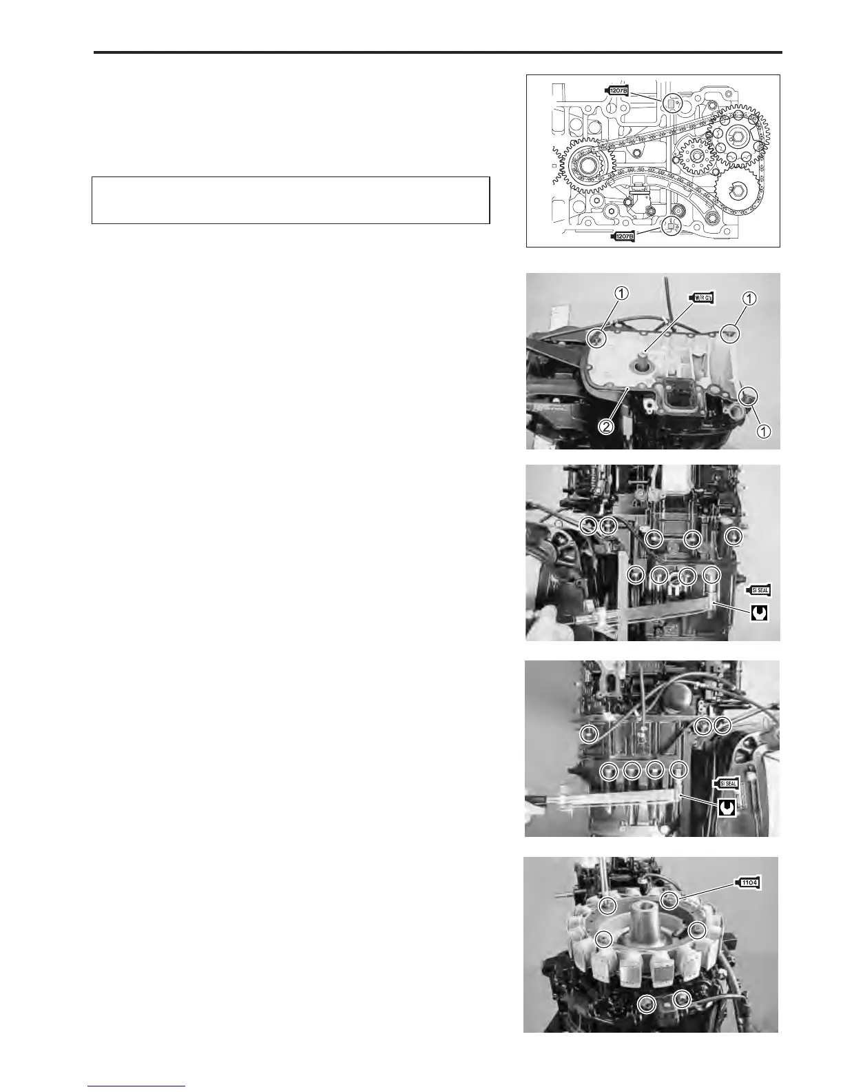
1. Install dowel pins 1 and gasket 2.
2. Apply Suzuki Water Resistant Grease to driveshaft splines.
N 99000-25161 : Suzuki Water Resistant Grease
NOTE:
Before installing power unit, apply Suzuki Bond to hatched part
(2 parts) as shown in figure.
D 99000-31140 : Suzuki Bond 1207B
3. Lower power unit onto engine holder.
NOTE:
Rotate crankshaft to aid alignment of driveshaft and counter
shaft splines.
4. Apply Suzuki Silicone Seal to power unit mounting bolts
and tighten bolts to specified torque.
N 99000-31120 : Suzuki Silicone Seal
" Power unit mounting bolt :
8 mm 23 N
.
m (2.3 kg-m, 16.5 lb.-ft.)
10 mm 50 N
.
m (5.0 kg-m, 36.0 lb.-ft.)
FLYWHEEL
1. Install battery charge coil. (See page 4-6)
2. Install CKP sensor. (See page 3-53)