3-6 ENGINE CONTROL SYSTEM
IAC valve solenoid (–)
B/ R
No.2 Ignition coil (–)
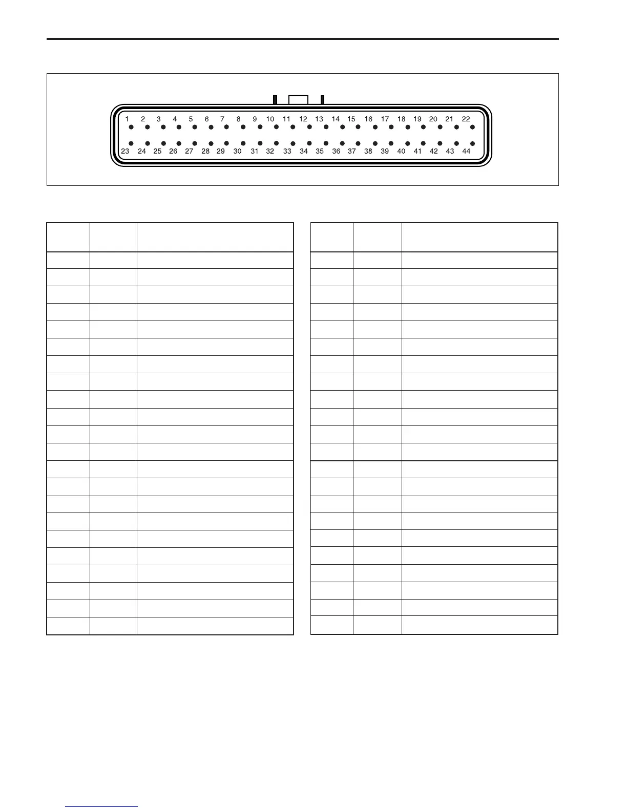
ECM CONNECTOR / TERMINALS LAYOUT
ECM CIRCUITS
TERMI-
NAL
WIRE
COLOR
CIRCUIT
1—
2 Bl/R Emergency stop switch
3 O Buzzer cancel
4 Y / B Tachometer
5 Br Neutral switch
6—
7 V/ W Ex-manifold temp. sensor
8—
—
9 Lg/W Cylinder temp. sensor
10 B Ground for ECM
11 B / W Ground for sensors
12 Bl/B Oil lamp
13 P / B Ground for ECM main relay
14 —
15 R / B CKP sensor
16 O/Y PC communication
17 G/Y TEMP lamp
18
19 —
20 B Ground for ignition coil
21 —
22 Lg No.4 Fuel injector (–)
39 B / Y No.2 Fuel injector (–)
40 O/ B No.1 Fuel injector (–)
41
42 B
Ground for ignition coil
TERMI-
NAL
WIRE
COLOR
CIRCUIT
23 Bl Oil pressure switch
24 Lg/R CTP switch
25 P REV-LIMIT lamp
26 G / W CHECK ENGINE lamp
27 Bl/W Buzzer
28 —
29 W MAP sensor
30 Gr ECM power source
31 Lg/B IAT sensor
32 B Ground for ECM
33 O/ G CMP sensor
34 B/G
O
2
feedback / PC communication
35 R Power source for MAP sensor
36 Y PC communication
37 B / W Fuel pump (–)
38 R/W No.3 Fuel injector (–)
43
44
Bl
O No.1 Ignition coil (–)
—
—
—
—
—
—
——