6-54 POWER UNIT
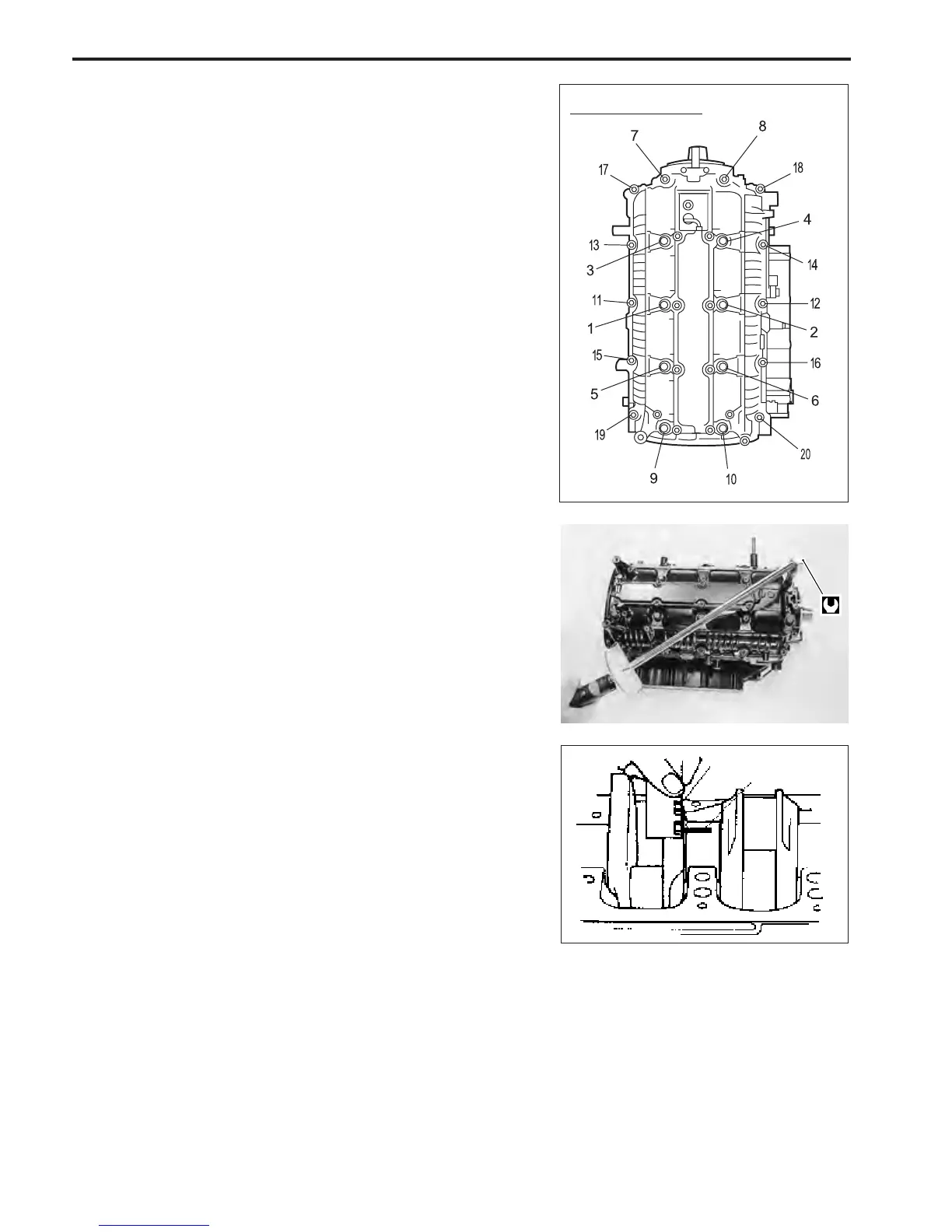
6. Apply engine oil lightly to crankcase bolts.
Tighten crankcase bolts in three (3) steps according to the
order shown below and in figure.
""
""
" Crankcase bolt :
1st step 8 mm 5 N
.
m (0.5 kg-m, 3.5 lb.-ft.)
10 mm 11 N
.
m (1.1 kg-m, 8.0 lb.-ft.)
2nd step 8 mm 20 N
.
m (2.0 kg-m, 14.5 lb.-ft.)
10 mm 43 N
.
m (4.3 kg-m, 31.0 lb.-ft.)
Final step 8 mm 25 N
.
m (2.5 kg-m, 18.0 lb.-ft.)
10 mm 56 N
.
m (5.6 kg-m, 40.5 lb.-ft.)
NOTE:
• Crankcase should be torqued to specification in order to
assure proper compression of Plastigauge and accurate
reading of clearance.
• Do not rotate crankshaft while Plastigauge is installed.
7. Remove crankcase from cylinder.
8. Using scale on Plastigauge envelope, measure Plastigauge
width at its widest point.
Crankshaft journal oil clearance :
Standard : 0.020 – 0.040 mm (0.0008 – 0.0016 in.)
Service limit : 0.065 mm (0.0026 in.)
If measurement exceeds service limit, replace crankshaft main
bearing.
NOTE:
For bearing replacement, see “SELECTION OF MAIN BEAR-
ING” section on page 6-55.
Scale
Plastigauge
5. Install crankcase to cylinder.
Tightening order
 Loading...


