3-40 ENGINE CONTROL SYSTEM
Injector Terminal
No.1 40
No.2
39
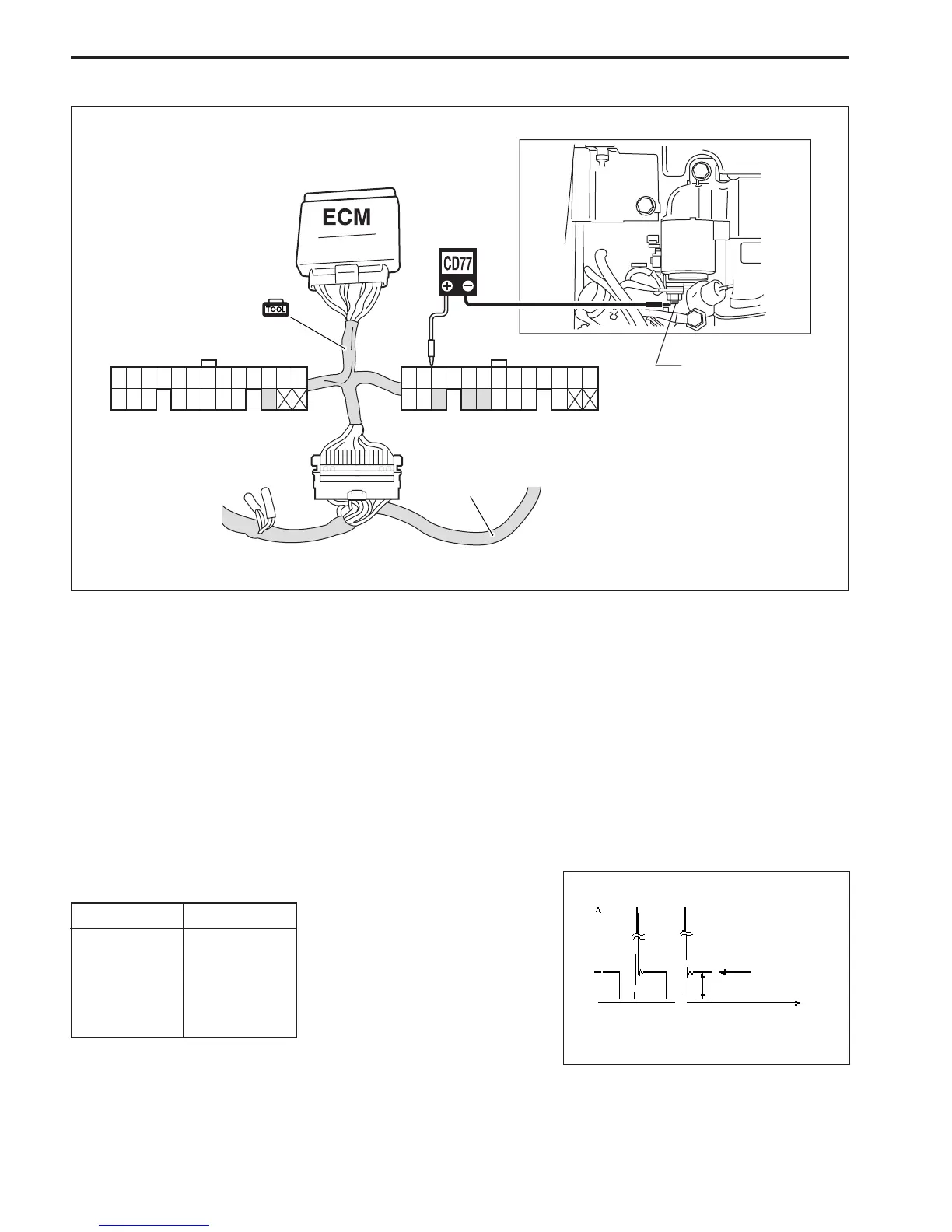
4. Crank engine and measure voltage.
Fuel injector operating signal : 6 – 10 V
3. Connect tester probe + (Red) to each terminal.
\ 09930-89950 : 44-pin test cord
S Peak voltmeter Stevens CD-77
Tester range : NEG50
1. Connect test cord between ECM and wire harness as shown
in figure, then turn ignition switch ON.
2. Connect tester probe - (Black) to starter motor magnetic
switch “B” terminal (connected to battery positive + termi-
nal) as shown in figure.
(Voltage)
12V
(Time)
A
B
A Peak voltage reading (NEG)
B 0V level for peak voltmeter
No.3
No.4
38
22
FUEL INJECTOR OPERATING SIGNAL
1 2 3 4 5 6 7 8 9 10 11 12 13
14 15 16 17 18 19 20 21 22
23 24 25 26 27 28 29 30 31 32 33 34 35
36 37 38
39 40 41 42 43 44
Wire harness
Starter motor magnetic
switch “B” terminal
(Black connector)
(White connector)
22
38 39 40



 To Next Page