AUTOMATIC TRANSMISSION (4 A/T) 7B-27
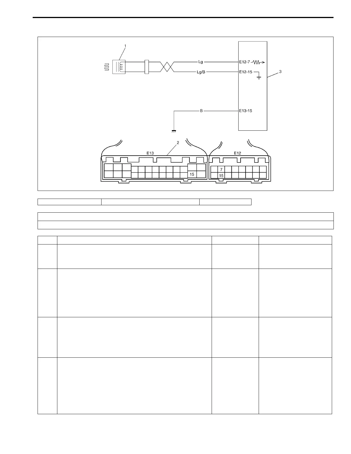
DTC P0715 Input/turbine speed sensor circuit malfunction
1. Input shaft speed sensor 2. TCM couplers (viewed from harness side) 3. TCM
DTC DETECTING CONDITION
• Input shaft speed sensor signal voltage too high or too low.
Step Action Yes No
1 Was “AUTOMATIC TRANSMISSION DIAGNOSTIC
FLOW TABLE” performed?
Go to Step 2. Go to “AUTOMATIC
TRANSMISSION DIAG-
NOSTIC FLOW TABLE”.
2 1) Turn ignition switch OFF and disconnect output shaft
speed sensor – input shaft speed sensor coupler.
2) Measure resistance between terminals of the discon-
nected sensor side coupler.
Is it 160 – 200 Ω?
(See figure.)
Go to Step 3. Replace input shaft speed
sensor.
3 1) Connect output shaft speed sensor - input shaft
speed sensor coupler then disconnect TCM couplers.
2) Measure resistance between terminal “E12-7” and
“E12-15” of disconnected harness side coupler.
Is it 160 – 200 Ω?
Go to Step 4. “Lg” or “Lg/B” wire open
or shorted each other.
4 Measure resistance between terminal “E12-7” (of discon-
nected harness side coupler) and body ground then ter-
minal “E12-15” (of disconnected harness side coupler)
and body ground.
Are they about 0 Ω?
(See figure.)
Short in
between “Lg”
wire and ground
or “Lg/B” wire
and ground.
Poor connection of termi-
nal “E12-7” or “E12-15” of
TCM.
If all the above are in good
condition, substitute a
known-good TCM and
recheck.