AUTOMATIC TRANSMISSION (4 A/T) 7B-39
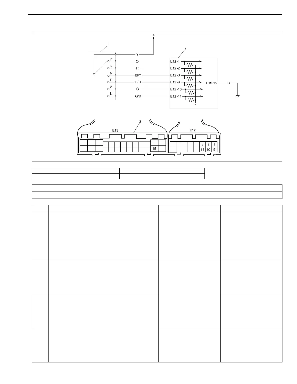
DTC P0705 Transmission range sensor (switch) circuit malfunction
1. Transmission range sensor (shift switch) 3. TCM couplers (viewed from harness side)
2. TCM 4. Power source
DTC DETECTING CONDITION
• No shift switch signal inputted or two or more shift switch signals inputted at the same time.
Step Action Yes No
1 1) Turn ignition switch OFF, disconnect TCM
couplers.
2) Turn ignition switch ON, check voltage
between terminal “E12-1” and “E13-15” of
disconnected harness side TCM coupler.
Is it 10 – 14 V at “P” range and 0 V at the other
range?
Go to Step 2. Go to Step 7.
2 While ignition switch ON, check voltage
between terminal “E12-2” and “E13-15” of dis-
connected harness side TCM coupler.
Is it 10 – 14 V at “R” range and 0 V at the other
range?
Go to Step 3. Go to Step 7.
3 While ignition switch ON, check voltage
between terminal “E12-3” and “E13-15” of dis-
connected harness side TCM coupler.
Is it 10 – 14 V at “N” range and 0 V at the other
range?
Go to Step 4. Go to Step 7.
4 While ignition switch ON, check voltage
between terminal “E12-9” and “E13-15” of dis-
connected harness side TCM coupler.
Is it 10 – 14 V at “D” range and 0 V at the other
range?
Go to Step 5. Go to Step 7.