AUTOMATIC TRANSMISSION (4 A/T) 7B-45
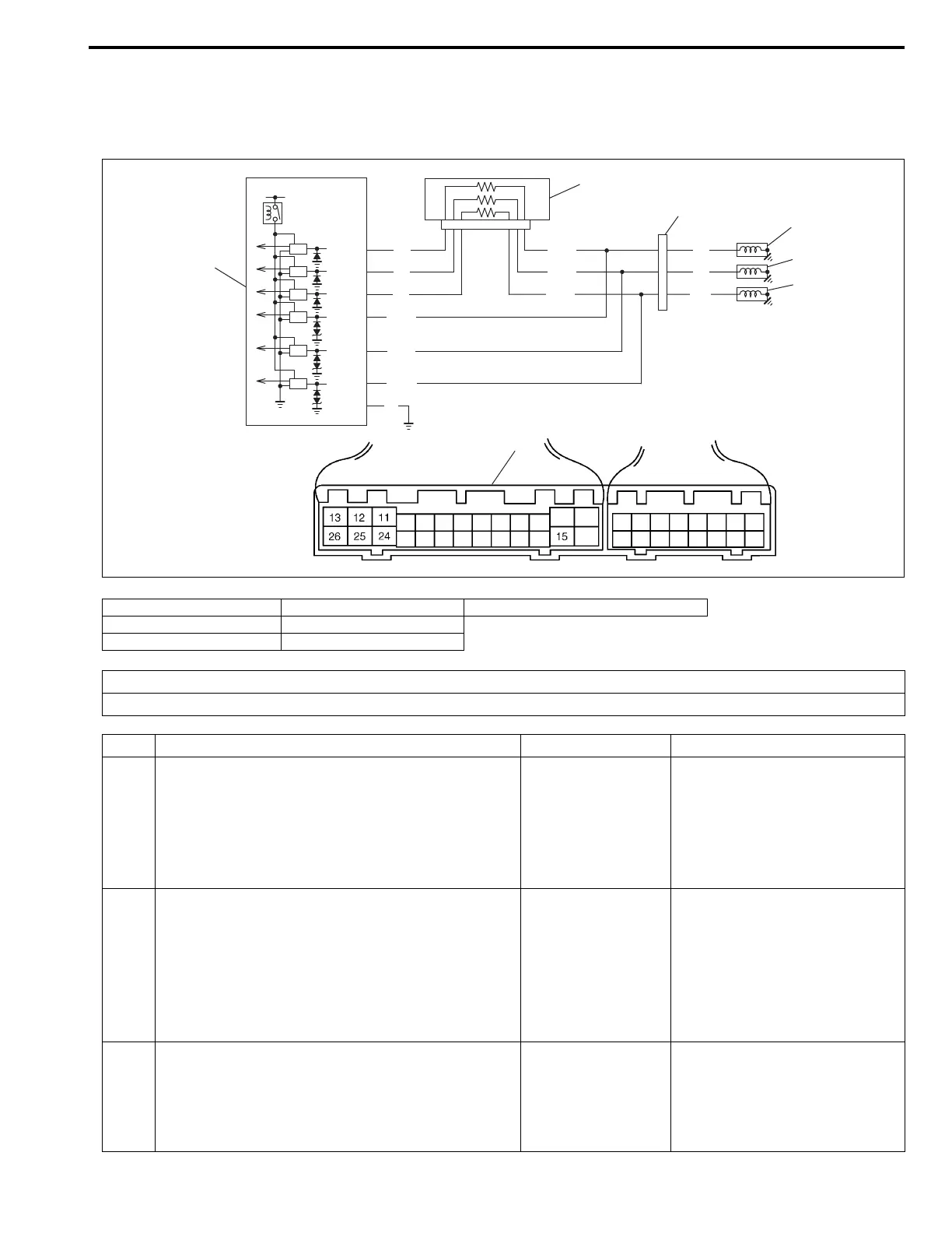
DTC P0763 Shift solenoid-C (No.3) electrical
DTC P0768 Shift solenoid-D (No.4) electrical
DTC P0773 Shift solenoid-E (No.5) electrical
1. Dropping resistor 4. Shift solenoid valve-D (No.4) 7. TCM couplers (viewed from harness side)
2. solenoid coupler 5. Shift solenoid valve-E (No.5)
3. Shift solenoid valve-C (No.3) 6. TCM
12V
E13-24
E13-13
E13-12
E13-11
E13-25
E13-26
E13-15
1
6
2
3
4
5
R/WR
Y
W
R/W
Y/Bl
W/Bl
Y/Bl
W/Bl
B
R
Y
Br
7
E13
E12
DTC DETECTING CONDITION
• Solenoid output voltage too high or too low differently from TCM order.
Step Action Yes No
1 1) Turn ignition switch OFF and disconnect sole-
noid coupler.
2) Measure resistance between terminal of sole-
noid coupler and transmission ground. (See
figure.)
Is it 2.0 – 4.0 Ω?
Go to Step 2. • Solenoid lead wire open or
shorted to ground.
• Malfunction of solenoid
valve.
2 1) Disconnect TCM couplers.
2) Measure resistance between terminal of dis-
connected body side solenoid coupler and
terminal “E13-11”, “E13-12” or “E13-13” of
disconnected harness side TCM coupler.
(See chart.)
Is it 6.5 – 8.5 Ω?
Go to Step 3. Inspect dropping resister refer-
ring to “DROPPING RESIS-
TOR” in this section.
If OK, circuit between TCM
and dropping resister or drop-
ping resister and solenoid cou-
pler open.
3 Check continuity between terminal “E13-24”,
“E13-25” or “E13-26” of disconnected TCM cou-
pler and terminal of disconnected body side sole-
noid coupler. (See chart.)
Is there continuity?
Go to Step 4. Circuit between TCM and sole-
noid coupler open.