7B-46 AUTOMATIC TRANSMISSION (4 A/T)
Chart for Step 2
Chart for Step 3
Chart for Step 5
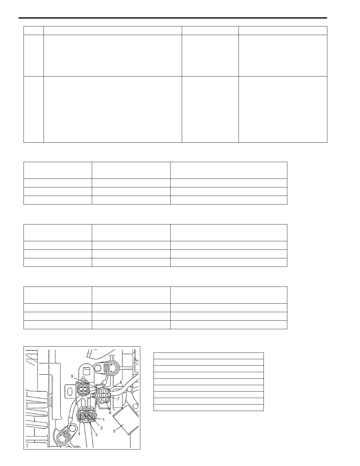
Figure for Step 1 and 5
4 Check continuity between terminal of discon-
nected body side solenoid coupler and transmis-
sion ground with TCM, dropping resister and
solenoid couplers disconnected.
Is there continuity?
Circuit between
TCM and transmis-
sion shorted to
ground.
Go to Step 5.
5 Check continuity between terminal of discon-
nected body side dropping resistor coupler and
transmission ground. (See chart.)
Is there continuity?
Circuit between
TCM and dropping
resister is shorted
to ground.
Intermittent trouble or faulty
TCM.
Check for intermittent referring
to “INTERMITTENT AND
POOR CONNECTION” in Sec-
tion 0A. If no trouble found,
substitute a known-good TCM
and recheck.
Solenoid TCM terminal No.
Solenoid coupler lead wire color
(body side)
C (No.3) E13-11 R/W
D (No.4) E13-12 Y/Bl
E (No.5) E13-13 W/Bl
Solenoid TCM terminal No.
Solenoid coupler lead wire color
(body side)
C (No.3) E13-24 R/W
D (No.4) E13-25 Y/Bl
E (No.5) E13-26 W/Bl
Solenoid TCM terminal No.
Dropping resistor lead wire color
(body side)
C (No.3) E13-11 R
D (No.4) E13-12 Y
E (No.5) E13-13 W
1. Solenoid coupler
2. Terminal for shift solenoid-C (No.3)
3. Terminal for shift solenoid-D (No.4)
4. Terminal for shift solenoid-E (No.5)
5. Transmission range sensor (Shift switch)
6. Dropping resistor terminal for shift solenoid-C (No.3)
7. Dropping resistor terminal for shift solenoid-D (No.4)
8. Dropping resistor terminal for shift solenoid-E (No.5)
9. Dropping resistor coupler
Step Action Yes No