5E-26 ANTILOCK BRAKE SYSTEM (ABS)
DTC C1041 – Right-Front Inlet Solenoid Circuit
DTC C1045 – Left-Front Inlet Solenoid Circuit
DTC C1051 – Right-Rear Inlet Solenoid Circuit
DTC C1055 – Left-Rear Inlet Solenoid Circuit
DTC C1042 – Right-Front Outlet Solenoid Circuit
DTC C1046 – Left-Front Outlet Solenoid Circuit
DTC C1052 – Right-Rear Outlet Solenoid Circuit
DTC C1056 – Left-Rear Outlet Solenoid Circuit
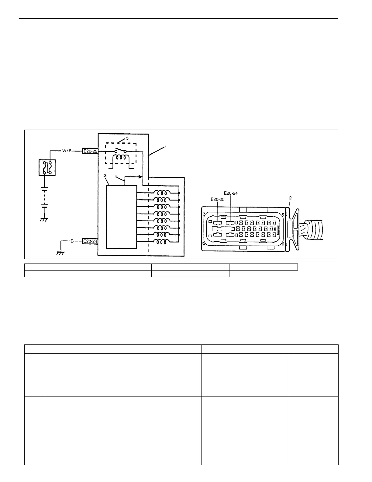
DESCRIPTION
The ABS control module monitors the output from the valve.
When the output of each valve exceeds the specified value compared with the signal sent from ABS control
module, this DTC is set.
INSPECTION
1. ABS hydraulic unit/control module assembly 3. ABS control module 5. Fail-safe relay
2. ABS hydraulic unit/control module assembly connector 4. Signal
Step Action Yes No
1 1) Check solenoid operation referring to item “ABS
HYDRAULIC UNIT OPERATION CHECK” in this
section.
Is it in good condition?
Check terminal “E20-25” con-
nection. If connection is OK,
substitute a known-good ABS
hydraulic unit/control module
assembly and recheck.
Go to Step 2.
2 1) Turn ignition switch to OFF position.
2) Disconnect ABS hydraulic unit/control module con-
nector.
3) Check for proper connection to ABS hydraulic unit/
control module connector at terminal “E20-25”.
4) If OK, then measure voltage between terminal
“E20-25” of module connector and “E20-24”.
Is it 10 – 14 V?
Substitute a known-good
ABS hydraulic unit/control
module assembly and
recheck.
“WHT/BLU” or
“BLK” circuit
open.