5E-28 ANTILOCK BRAKE SYSTEM (ABS)
DTC C1061 – ABS Pump Motor Circuit
DESCRIPTION
The ABS control module monitors the voltage at monitor terminal of pump motor circuit constantly with the igni-
tion switch turned ON. It sets this DTC when the voltage at the monitor terminal does not become high/low
according to ON/OFF commands to the motor relay of the module (does not follow these commands).
INSPECTION
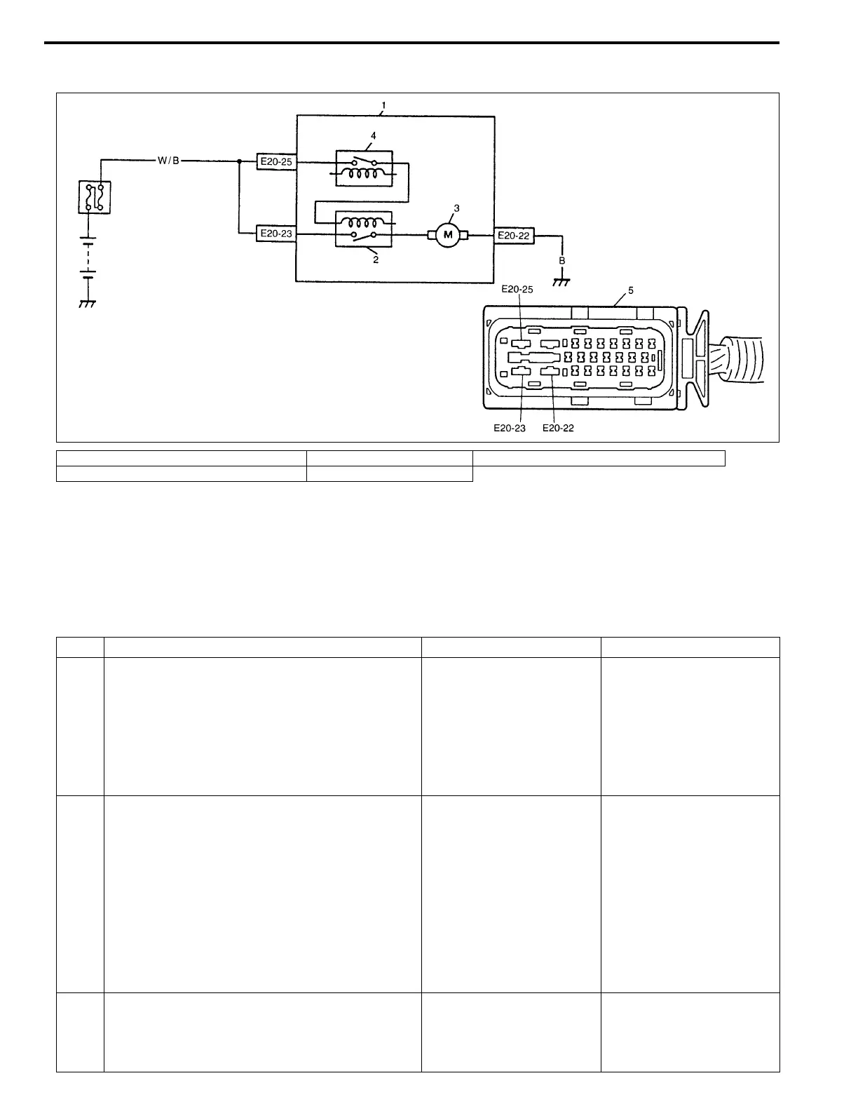
1. ABS hydraulic unit/control module assembly 3. ABS pump motor 5. ABS hydraulic unit/control module connector
2. ABS pump motor relay 4. ABS fail safe relay
Step Action Yes No
1 1) Check pump motor referring to “ABS
HYDRAULIC UNIT OPERATION CHECK”
in this section.
Is it in good condition?
Check terminals “E20-25”
and “E20-23” connection.
If connections OK, substi-
tute a known-good ABS
hydraulic unit/control
module assembly and
recheck.
Go to Step 2.
2 1) Turn Ignition switch to OFF position.
2) Disconnect ABS hydraulic unit/control mod-
ule connector.
3) Check for proper connection to ABS hydrau-
lic unit/control module connector at terminal
“E20-23”.
4) If OK, then measure voltage between termi-
nal “E20-23” of module connector and body
ground.
Is it 10 – 14 V?
Go to Step 3. “W/B” circuit open.
3 Measure resistance between terminal “E20-22”
of ABS hydraulic unit/control module connector
and body ground.
Is it infinite (∞)?
“B” circuit open. Substitute a known-good
ABS hydraulic unit/con-
trol module assembly and
recheck.