10B-22 AIR BAG SYSTEM
DTC B1015 – Passenger Air Bag Initiator Circuit Resistance High
DTC B1016 – Passenger Air Bag Initiator Circuit Resistance Low
DTC B1018 – Passenger Air Bag Initiator Circuit Short to Ground
DTC B1019 – Passenger Air Bag Initiator Circuit Short to Power Circuit
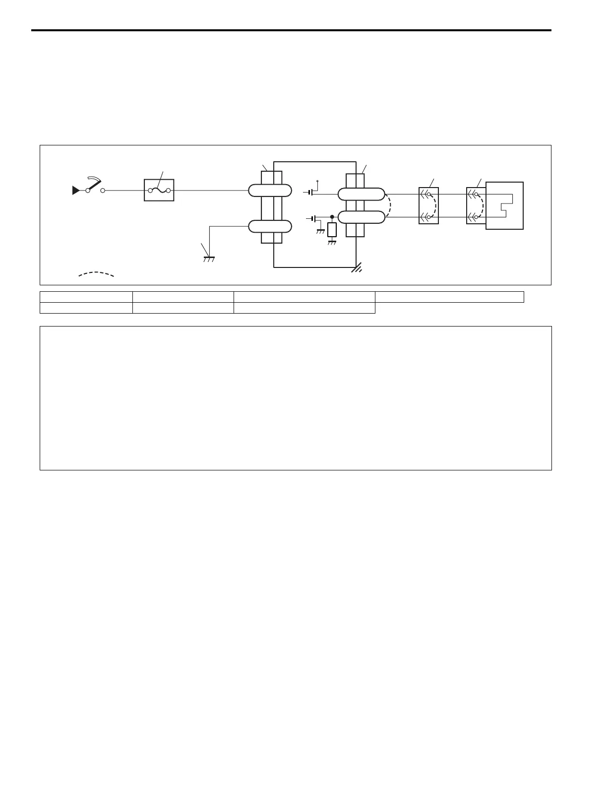
WIRING DIAGRAM
DTC WILL SET WHEN
DTC B1015 :
The combined resistance of the passenger air bag (inflator) module, harness wiring and connector terminal con-
tact is above a specified value for specified time.
DTC B1016 :
The combined resistance of the passenger air bag (inflator) module, harness wiring and connector terminal con-
tact is below a specified value for specified time.
DTC B1018 :
The voltage measured at passenger air bag initiator circuit is below a specified value for specified time.
DTC B1019 :
The voltage measured at passenger air bag initiator circuit is above a specified value for specified time.
TABLE TEST DESCRIPTION
DTC B1015, B1016, B1018 or B1019 :
STEP 1 : Check whether malfunction is in passenger air bag (inflator) module.
STEP 2 : Check passenger air bag (inflator) module initiator circuit in air bag harness (in instrument panel har-
ness).
STEP 3 : Check passenger air bag (inflator) module initiator circuit in air bag harness (in instrument panel har-
ness). (for DTC B1018 and B1019 only)
[A]: Shorting bar 2. Ignition switch 4. SDM 6. Ground for air bag system
1. From main fuse 3. “AIR BAG” fuse 5. Passenger air bag (inflator) module
GRN
YEL/RED
YEL
BLU/RED
BLK
“X01”“G74”
“G66”
“G66”
+12V
G66-32
G66-31
G66-24
G66-23
1
2
3
6
4
5
[A]
CAUTION:
• Be sure to perform AIR BAG DIAGNOSTIC SYSTEM CHECK before starting diagnosis according to
flow table.
• When measurement of resistance or voltage is required in this table, use a specified digital multim-
eter (refer to SPECIAL TOOL in this section.) along with a correct terminal adaptor from special tool
(Connector test adapter kit).
• When a check for proper connection is required, refer to INTERMITTENTS AND POOR CONNEC-
TIONS in this section.
• If there is open circuit in the air bag wire harness (in instrument panel harness), connector or termi-
nal is found damaged, replace the wire harness, connector and terminal as an assembly.