IGNITION SYSTEM (ELECTRONIC IGNITION SYSTEM) 6F1-7
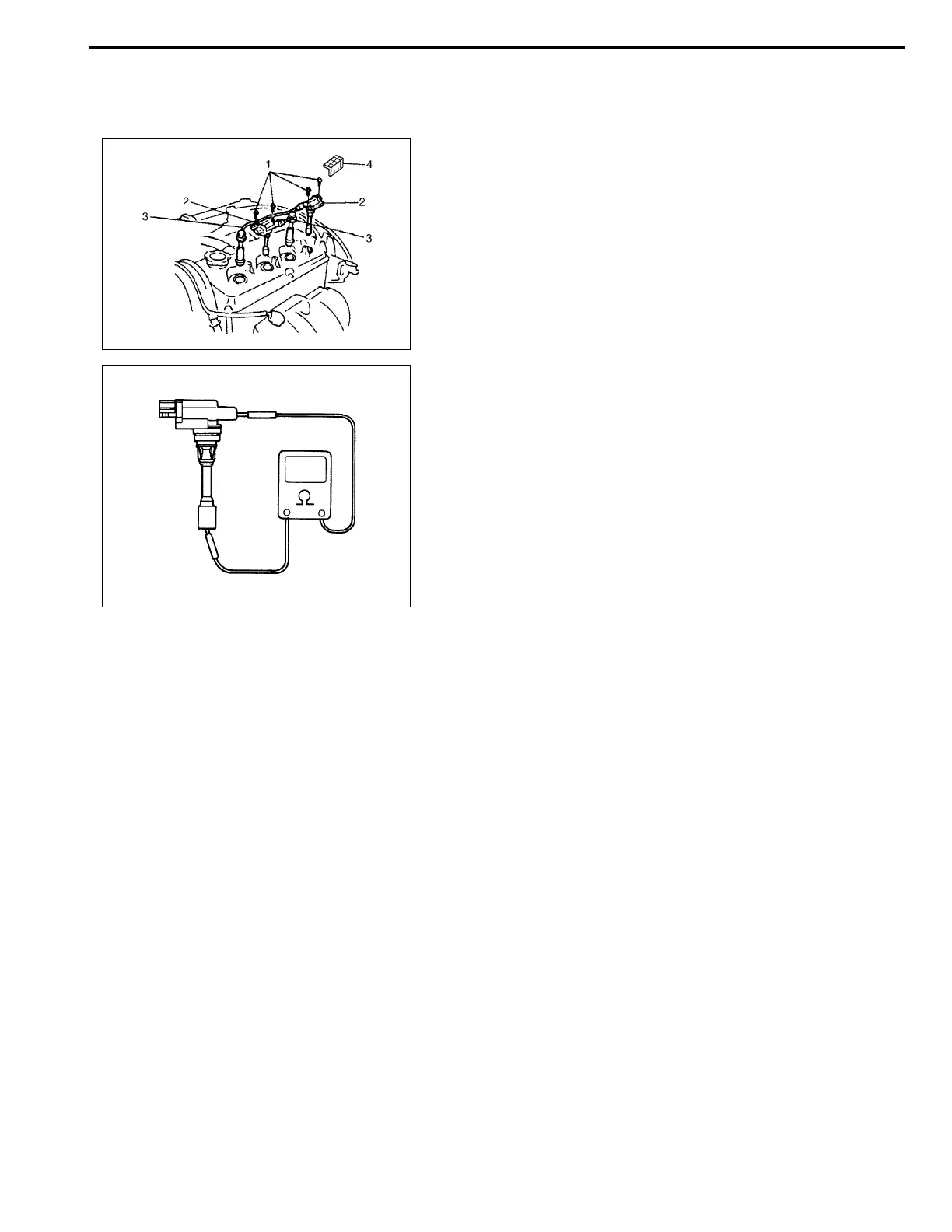
Ignition coil assembly (including ignitor)
Inspection
1) Disconnect negative cable at battery.
2) Pull out ignition coil cover (4).
3) Disconnect ignition coil coupler.
4) Disconnect high-tension cord (3) from ignition coil assembly
(2).
5) Remove ignition coil bolts (1) and then pull out ignition coil
assembly.
6) Measure secondary coil for resistance.
Secondary coil resistance
: 8.5 – 11.5 kΩ at 20°C, 68°F
If resistance is out of specification, replace ignition coil assembly.
7) Install ignition coil assembly.
8) Tighten ignition coil bolts, and then connect ignition coil cou-
pler.
9) Install high-tension cord to ignition coil assembly while grip-
ping its cap.
10) Install ignition coil cover certainly to ignition coil assembly.
Crankshaft position sensor (CKP sensor)
Refer to section 6E for removal, inspection and installation.
Ignition timing
NOTE:
• Ignition timing is not adjustable. If ignition timing is
out of specification, check system related parts.
• Before starting engine, place transmission gear shift
lever in “Neutral” (shift selector lever to “P” range for
A/T model), and set parking brake.