AIR BAG SYSTEM 10B-5
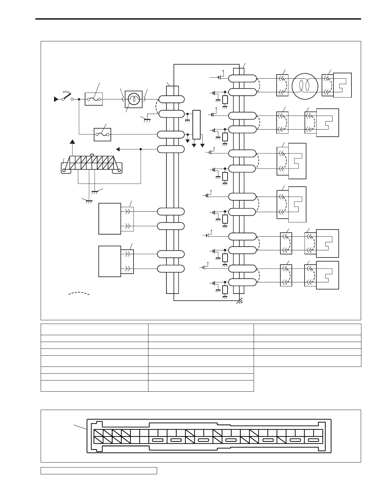
System Wiring Diagram
TERMINAL ARRANGEMENT OF SDM CONNECTOR (VIEWED FROM HARNESS SIDE)
[A] : Shorting bar 8. Ground for air bag system 16. Side air bag (inflator) module
at passenger side (if equipped)
1. From main fuse 9. SDM 17. Side sensor at driver side (if equipped)
2. Ignition switch 10. Contact coil assembly 18. Side sensor at passenger side (if equipped)
3. “METER” fuse 11. Driver air bag (inflator) module 19. Ground on body
4. “AIR BAG” warning lamp in combination meter 12. Passenger air bag (inflator) module (if
equipped)
20. Ground on engine block
5. “AIR BAG” fuse 13. Driver seat belt pretensioner
6. To ECM and ABS control module (if equipped) 14. Passenger seat belt pretensioner
7. Data link connector (DLC) 15. Side air bag (inflator) module
at driver side (if equipped)
1. SDM connector “G66”
GRN
GRN
BLK/RED
BLU
GRN/RED
GRN
YEL/RED
YEL
PNK
WHT
BLU/RED
+30V
+12V
+5V
WHT/RED
WHT/RED
“G67”
“G68”
“G71”
GRN/WHT
GRN/BLK
GRN/YEL
GRN/ORN
BLK
“G65”
“G66”
“Q08”
BRN
LT GRN
“G72”
WHT/RED
WHT/GRN
“G69”
RED/BLK
RED/YEL
“G70”
“G66”
+12V
+12V
+12V
+12V
+12V
G66-30
G66-32
G66-28
G66-17
G66-6
G66-16
G66-5
G66-31
G66-24
G66-23
G66-27
G66-26
G66-33
G66-34
G66-36
G66-35
G66-19
G66-18
G66-20
G66-21
BLK
BRN
WHT/BLU
“G25”
“G25”
[A]
“G74”
17
18
20
19
7
6
5
8
4
2
1
3
9
10
11
12
“X01”
“X02”
13
14
“X03”
15
16
1
16
5
1
17
6
18 19 20 21 23 24 26 27 28 30 31 32 33 34 35 36