AIR BAG SYSTEM 10B-57
DTC B1081 – Side Air Bag (Driver Side) Intiator Circuit Resistance High
DTC B1082 – Side Air Bag (Driver Side) Intiator Circuit Resistance Low
DTC B1083 – Side Air Bag (Driver Side) Intiator Circuit Short to Ground
DTC B1084 – Side Air Bag (Driver Side) Intiator Circuit Short to Power Circuit
DTC B1085 – Side Air Bag (Passenger Side) Intiator Circuit Resistance High
DTC B1086 – Side Air Bag (Passenger Side) Intiator Circuit Resistance Low
DTC B1087 – Side Air Bag (Passenger Side) Intiator Circuit Short to Ground
DTC B1088 – Side Air Bag (Passenger Side) Intiator Circuit Short to Power Cir-
cuit
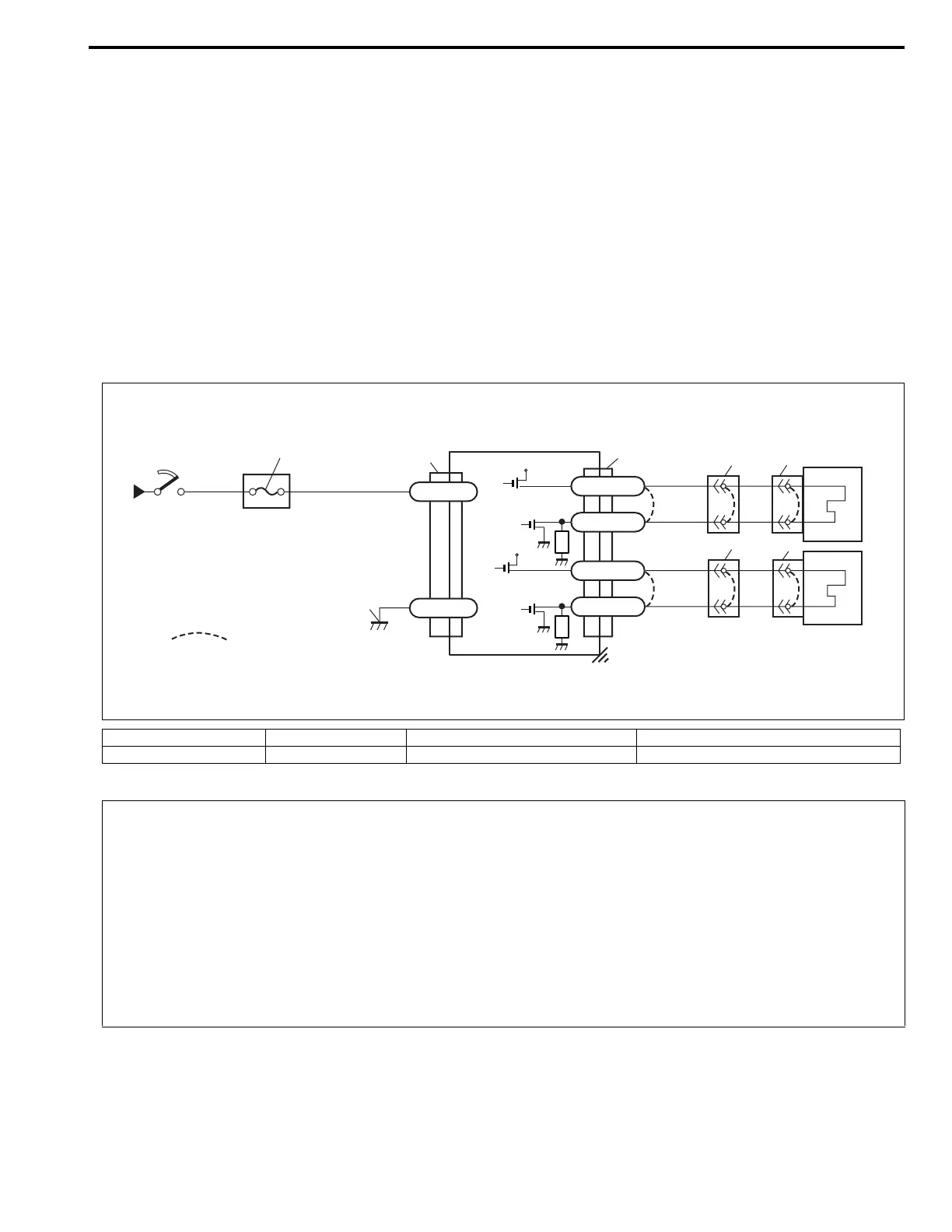
WIRING DIAGRAM
[A] : Shorting bar 2. Ignition switch 4. SDM 6. Side air bag (passenger side) (inflator) module
1. From main fuse 3. “AIR BAG” fuse 5. Side air bag (driver side) (inflator) module 7. Ground for air bag system
GRN
BLU/RED
BLK
“G66”
“G66”
+12V
+12V
G66-32
G66-31
G66-19
G66-18
G66-20
G66-21
[A]
3
7
WHT/RED
WHT/GRN
“G69”
RED/BLK
RED/YEL
“G70”
“X02”
4
“X03”
5
6
1
2
CAUTION:
• Be sure to perform AIR BAG DIAGNOSTIC SYSTEM CHECK before starting diagnosis according to
flow table.
• When measurement of resistance or voltage is required in this table, use a specified digital multim-
eter (refer to SPECIAL TOOL in this section.) along with a correct terminal adapter from special tool
(Connector test adapter kit).
• When a check for proper connection is required, refer to INTERMITTENTS AND POOR CONNEC-
TIONS in this section.
• If there is open circuit in the air bag wire harness (in instrument panel harness), connector or termi-
nal is found damaged, replace the wire harness, connector and terminal as an assembly.