WINDOWS, MIRRORS, SECURITY AND LOCKS 8D-5
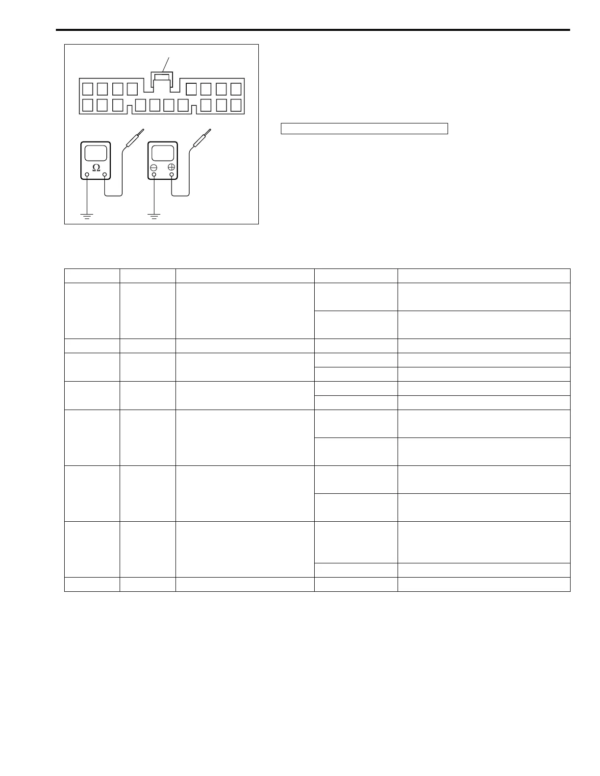
5) Check that the voltage and resistance between the following
terminals and body ground are specifications under each
conditions.
If check result is OK, replace door lock controller. If check
result is not as specified, repair circuit.
Power door lock system circuit check
1 : Power door lock controller coupler “G02”
91011
12
13 14
15
16 17 18
1234 56 7
8
1
V
Terminal Wire Circuit Specification Condition
G02-6 WHT Power door lock switch circuit
Continuity
Power door lock switch is pushing
position.
No continuity
Power door lock switch is free posi-
tion.
G02-9 WHT/GRN Main power supply 10 – 14 V –
G02-11 YEL/BLK Key remainder circuit
10 – 14 V Ignition key is in ignition switch.
0 – 1 V Ignition key is not in ignition.
G02-12 YEL Ignition switch circuit
10 – 14 V Ignition switch is ON position.
0 – 1 V Ignition switch is OFF position.
G02-13 WHT/BLK
Driver side key cylinder cir-
cuit (UNLOCK signal)
Continuity
Driver side key cylinder is UNLOCK
position.
No continuity
Except the above-mentioned condi-
tion.
G02-14 WHT/RED
Driver side key cylinder cir-
cuit (LOCK signal)
Continuity
Driver side key cylinder is LOCK
position.
No continuity
Except the above-mentioned condi-
tion.
G02-15 BLK/RED Door switch circuit
0 – 1 V
Driver side, passenger side, rear
driver side, rear passenger side or
back door is open.
10 – 14 V All doors are close.
G02-17 BLK Ground 0 – 1 V –