AIR BAG SYSTEM 10B-53
DTC B1073 – Side Sensor (Driver Side) Correspondence Abnormality
DTC B1075 – Side Sensor (Passenger Side) Correspondence Abnormality
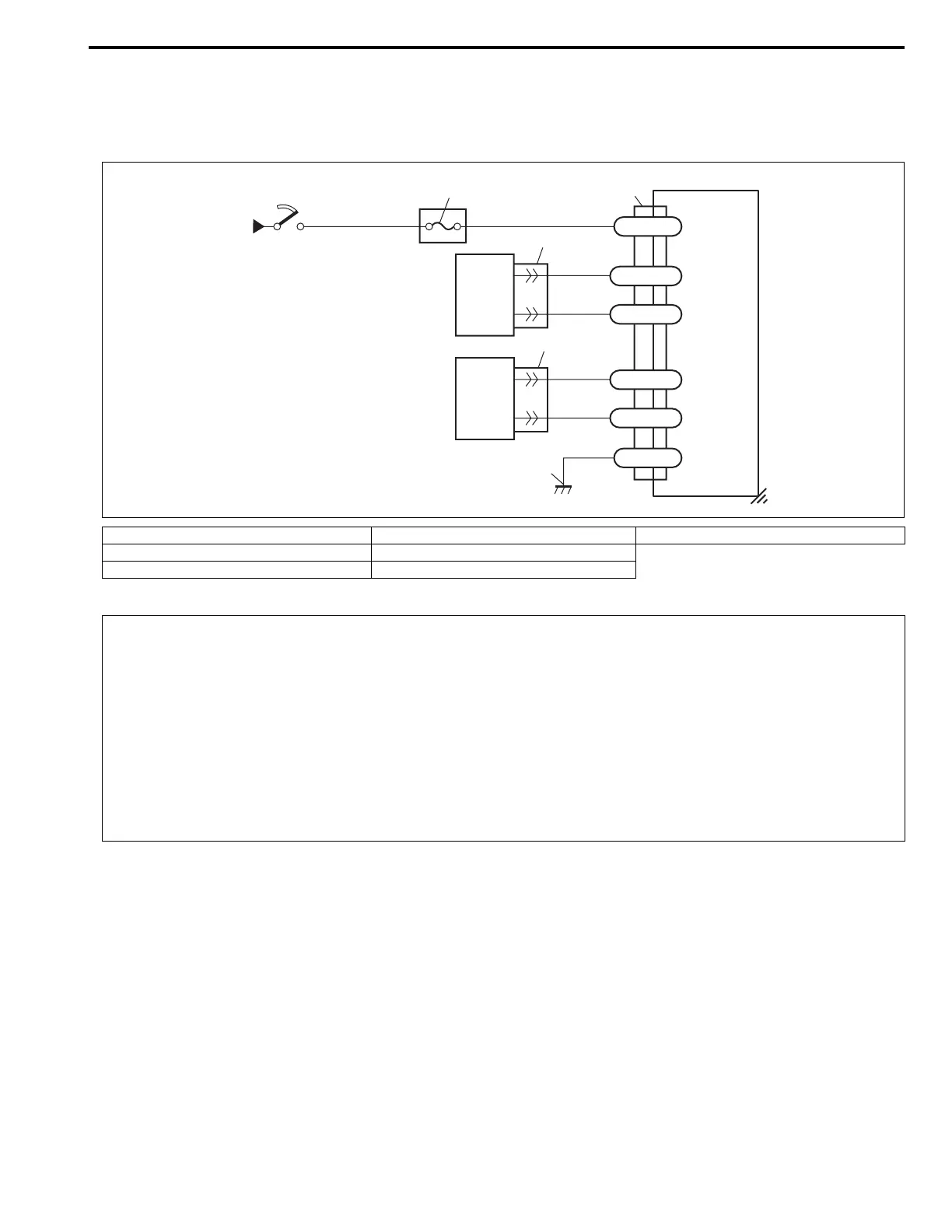
WIRING DIAGRAM
DTC WILL SET WHEN
DTC B1073 or B1075 :
Side sensor abnormal signal is detected by SDM.
TABLE TEST DESCRIPTION
DTC B1073 or B1075 :
STEP 1 to 4 : Check side sensor circuit in instrument panel harness.
1. From main fuse 4. SDM 7. Ground for air bag system
2. Ignition switch 5. Side sensor (driver side)
3. “AIR BAG” fuse 6. Side sensor (passenger side)
GRN
BLU/RED
“G68”
“G71”
GRN/WHT
GRN/BLK
GRN/YEL
GRN/ORN
BLK
“G66”
G66-32
G66-17
G66-6
G66-16
G66-5
G66-31
1
2
3
5
6
7
4
CAUTION:
• Be sure to perform AIR BAG DIAGNOSTIC SYSTEM CHECK before starting diagnosis according to
flow table.
• When measurement of resistance or voltage is required in this table, use a specified digital multim-
eter (refer to SPECIAL TOOL in this section.) along with a correct terminal adapter from special tool
(Connector test adapter kit).
• When a check for proper connection is required, refer to INTERMITTENTS AND POOR CONNEC-
TIONS in this section.
• If there is open circuit in the air bag wire harness (in instrument panel harness), connector or termi-
nal is found damaged, replace the wire harness, connector and terminal as an assembly.