AIR BAG SYSTEM 10B-27
DTC B1021 – Driver Air Bag Initiator Circuit Resistance High
DTC B1022 – Driver Air Bag Initiator Circuit Resistance Low
DTC B1024 – Driver Air Bag Initiator Circuit Short to Ground
DTC B1025 – Driver Air Bag Initiator Circuit Short to Power Circuit
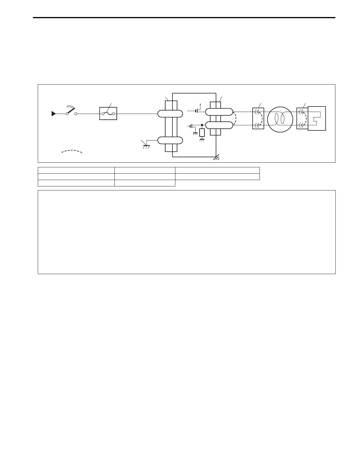
WIRING DIAGRAM
DTC WILL SET WHEN
DTC B1021 :
The combined resistance of the driver air bag (inflator) module, contact coil assembly, harness wiring and con-
nector terminal contact is above a specified value for specified time.
DTC B1022 :
The combined resistance of the driver air bag (inflator) module, contact coil assembly, harness wiring and con-
nector terminal contact is below a specified value for specified time.
DTC B1024 :
The voltage measured at driver air bag initiator circuit is below a specified value for specified time.
DTC B1025 :
The voltage measured at driver air bag initiator circuit is above a specified value for specified time.
TABLE TEST DESCRIPTION
DTC B1021, B1022, B1024 or B1025 :
STEP 1 : Check whether malfunction is in contact coil and driver air bag (inflator) module or the others.
STEP 2 : Check driver air bag (inflator) module initiator circuit in instrument panel harness.
STEP 3 : Check whether malfunction is in contact coil or driver air bag (inflator) module.
[A] : Shorting bar 3. “AIR BAG” fuse 6. Driver air bag (inflator) module
1. From main fuse 4. SDM 7. Ground for air bag system
2. Ignition switch 5. Contact coil assembly
GRN
GRN/RED
GRN
BLU/RED
+12V
BLK
“G65”
“G66”
“Q08”
“G66”
G66-32
G66-31
G66-27
G66-26
[A]
1
2
3
7
4
5
6
CAUTION:
Be sure to perform AIR BAG DIAGNOSTIC SYSTEM CHECK before starting diagnosis according to
flow table.
• When measurement of resistance or voltage is required in this table, use a specified digital multim-
eter (refer to SPECIAL TOOL in this section.) along with a correct terminal adapter from special tool
(Connector test adapter kit).
• When a check for proper connection is required, refer to INTERMITTENTS AND POOR CONNEC-
TIONS in this section.
• If there is open circuit in the air bag wire harness (in instrument panel harness), connector or termi-
nal is found damaged, replace the wire harness, connector and terminal as an assembly.