7B-32 AUTOMATIC TRANSMISSION (4 A/T)
Figure for Step 1
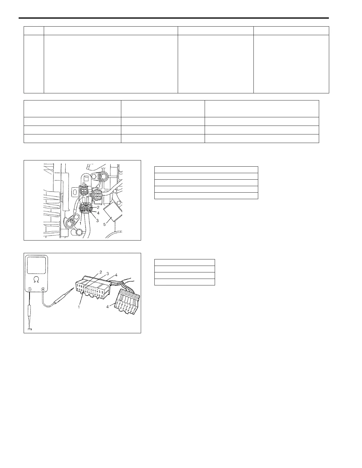
Figure for Step 2, 3, 4
4 Turn ignition switch ON then measure voltage
between terminal “E13-10”, “E13-23” or “E13-
22” of the disconnected harness side TCM cou-
pler and body ground.
Is it about 0 V?
Poor connection at termi-
nal “E13-10”, “E13-23” or
“E13-22” of TCM.
If all the above are in good
condition, substitute a
known-good TCM and
recheck.
“B/R”, “B/O” or “Br” wire or
shift solenoid lead wire
shorted to power source
circuit.
Step Action Yes No
Solenoid TCM Terminal Number
Lead Wire Color
(between TCM and solenoid coupler)
Shift solenoid -A (No.1) E13-10 B/R
Shift solenoid -B (No.2) E13-23 B/O
TCC solenoid (Lock-up solenoid) E13-22 Br
1. Shift solenoid -A (No.1) terminal
2. Shift solenoid -B (No.2) terminal
3. TCC (Lock-up) solenoid terminal
4. Solenoid coupler
5. Transmission range sensor (Shift switch)
1. “E13-10” terminal
2. “E13-23” terminal
3. “E13-22” terminal
4. TCM couples