AUTOMATIC TRANSMISSION (4 A/T) 7B-35
Figure for Step 1, 2
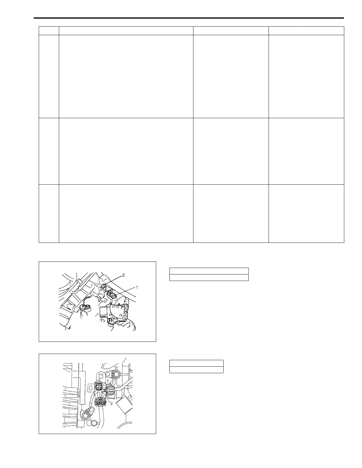
Figure for Step 2, 3
3 1) Disconnect output shaft speed sensor –
input shaft speed sensor coupler. (See fig-
ure.)
2) Measure resistance between terminal “3”
(of disconnected sensor side coupler) and
body ground then terminal “4” (of discon-
nected sensor side coupler) and body
ground.
Is it about 0 Ω?
(See figure.)
Replace output shaft
speed sensor.
Go to Step 4.
4 1) Connect output shaft speed sensor coupler.
2) Measure resistance between terminal “E12-
6” (of disconnected harness side coupler)
and body ground then terminal “E12-14” (of
disconnected harness side coupler) and
body ground.
Is it about 0 Ω?
(See figure.)
“W” or “B” wire shorted to
ground.
Go to Step 5.
5 Measure resistance between terminal “E12-6”
and “E12-13” (of disconnected harness side
coupler) then terminal “E12-14” and “E12-13”
(of disconnected harness side coupler).
Is it about 0 Ω?
(See figure.)
“W” wire or “B” wire
shorted to shield portion.
Poor connection of termi-
nal “E12-6” or “E12-14” of
the TCM.
If all the above are in good
condition, substitute a
known-good TCM and
recheck.
Step Action Yes No
1. Output shaft speed sensor
2. Input shaft speed sensor coupler
1. Terminal “3”
2. Terminal “4”