8C-2 INSTRUMENTATION/DRIVER INFORMATION
General Description
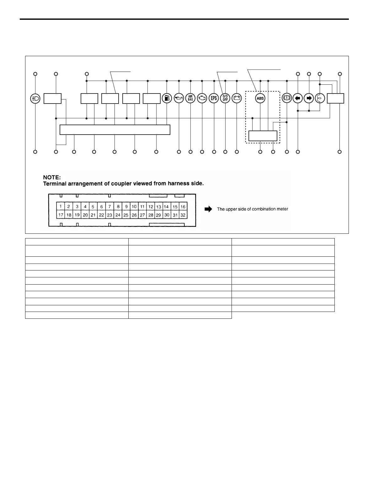
Combination Meter
1. To ground B 12. Blank – 23. To generator W/R
2. To ignition switch B/W 13. To dimmer switch R 24. To brake fluid level switch and
parking brake switch
Y/G
3. To ground B 14. Blank – 25. To A/T control module BI/Y
4. To SDM BI 15. To speed sensor V 26. To ECM V/W
5. Blank – 16. Blank – 27. To turn and hazard switch G/R
6. To oil pressure switch Y/B 17. To positive terminal at battery W/BI 28. To ignition switch (ACC) Y/B
7. To ABS control module O 18. To lighting switch R/Y 29. To positive terminal at battery W/BI
8. To EPS control module Gr 19. To ground Br 30. To door switch (driver side) B/O
9. Blank – 20. To fuel level gauge Y/R 31. To ECM Br/Y
10. To ABS control module BI/B 21. To ECT sensor W/G 32. Blank –
11. To turn and hazard switch G/Y 22. Blank –
SPEEDO
METER
Interface circuit
Voltage
regurator
FUEL
METER
TEMP.
METER
TACHO
METER
29
17
2
if equipped
if equipped
ABS/EBD circuit
(if equipped)
27 11
18
28
303247102325826462120311519113