ANTILOCK BRAKE SYSTEM (ABS) 5E-19
INSPECTION
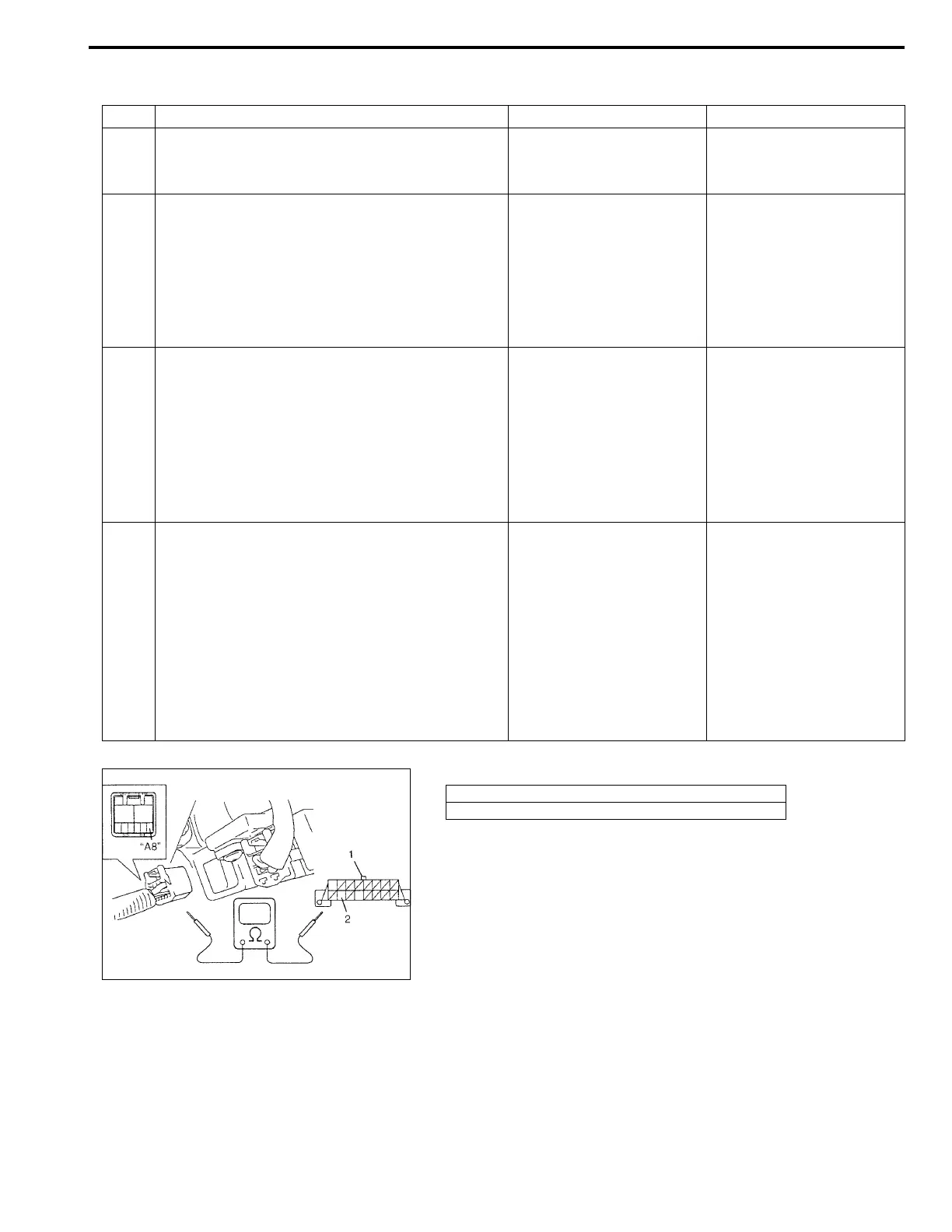
Fig. for Step 4
Step Action Yes No
1 Was “ABS DIAGNOSTIC CHECK FLOW
TABLE” performed?
Go to Step 2. Go to “ABS DIAGNOSTIC
CHECK FLOW TABLE” in
this section.
2 1) Make sure that SUZUKI scan tool is free
from malfunction and correct cartridge for
ABS is used.
1) Turn ignition switch to OFF position.
2) Check proper connection of SUZUKI scan
tool to DLC.
Is connection in good condition?
Go to Step 3. Properly connect SUZUKI
scan tool to DLC.
3 1) Check if communication is possible by try-
ing communication with other controller
(ECM, TCM, P/S control module or SDM).
Is it possible to communicate with other control-
ler?
Go to Step 4. Repair open in common
section of serial data cir-
cuit (“W/R” wire circuit)
used by all controllers or
short to ground or power
circuit which has occurred
somewhere in serial data
circuit (“W/R” wire circuit).
4 1) With ignition switch OFF position, discon-
nect ABS hydraulic unit/control module con-
nector from ABS hydraulic unit/control
module.
2) Check proper connection at “E20-21” (“W/
R” wire) terminal for serial data circuit.
3) If OK, then check resistance between “E20-
21” (“W/R” wire) terminal and “W/R” wire
terminal for serial data circuit in DLC.
Is resistance 1 Ω or less?
Substitute a known-good
P/S control module and
recheck.
Repair high resistance or
open in “W/R” wire circuit
for ANTI LOCK BRAKE
system.
1. DLC
2. “W/R” wire terminal