ANTILOCK BRAKE SYSTEM (ABS) 5E-33
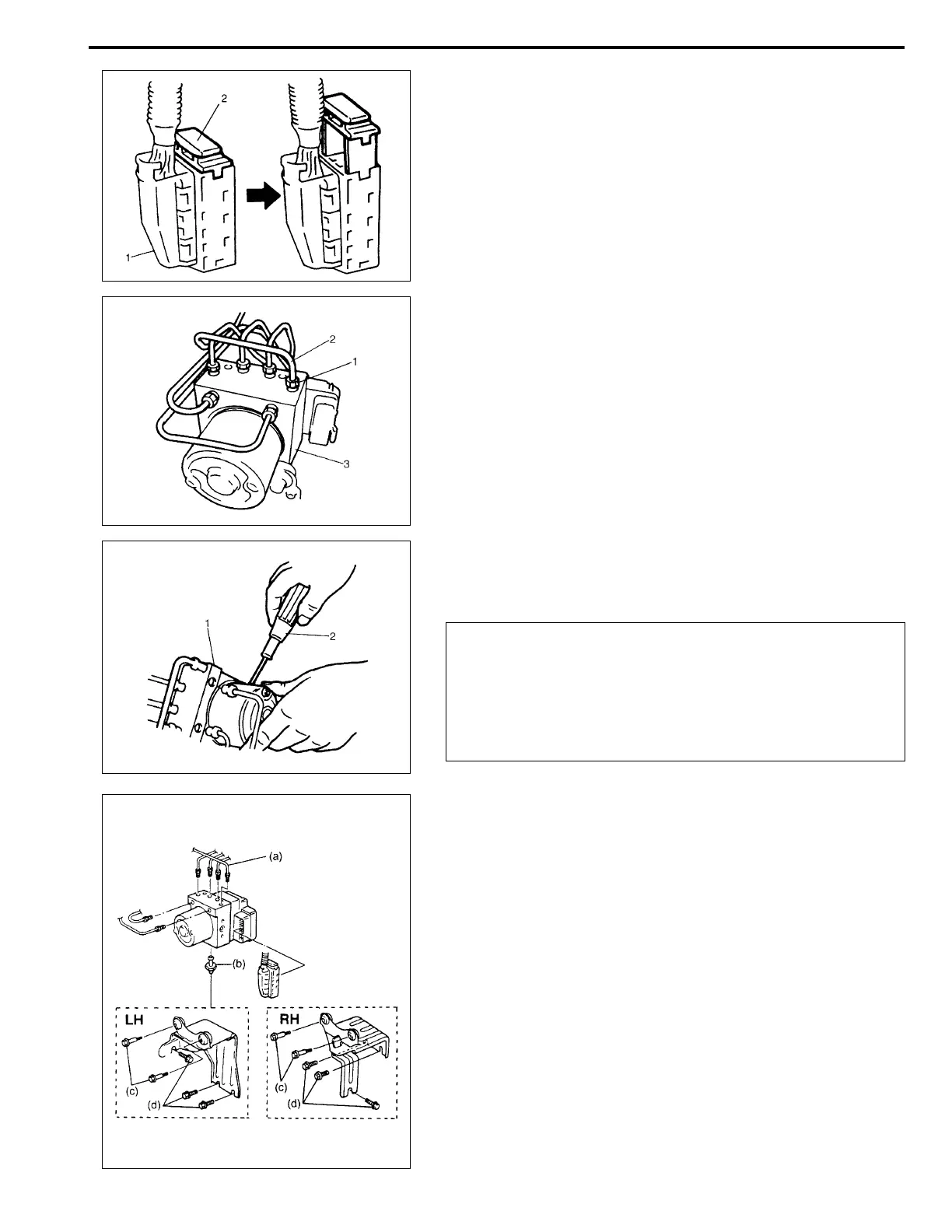
3) Disconnect ABS hydraulic unit/control module assembly con-
nector (1) by pulling up lock (2).
4) Using special tool, loosen flare nuts (1) and disconnect brake
pipes (2) from ABS hydraulic unit/control module assembly
(3).
Special tool
: 09950-78220
5) Remove two nuts and disconnect take out ABS hydraulic
unit/control module assembly (1) from bracket using screw-
driver (2).
INSTALLATION
1) Install hydraulic unit by reversing removal procedure.
Tightening torque
(a) : 16 N·m (1.6 kg-m, 11.5 lb-ft)
(b) : 9 N·m (0.9 kg-m, 6.5 lb-ft)
(c) : 9 N·m (0.9 kg-m, 6.5 lb-ft)
(d) : 26 N·m (2.6 kg-m, 18.0 lb-ft)
2) Bleed air from brake system referring to “BRAKE” section.
3) Check each installed part for fluid leakage and perform “ABS
Hydraulic Unit Operation Check” in this section.
NOTE:
Put bleeder plug cap onto pipe to prevent fluid from spill-
ing. Do not allow brake fluid to get on painted surfaces.
CAUTION:
• Do not give an impact to hydraulic unit.
• Use care not to allow dust to enter hydraulic unit.
• Do not place hydraulic unit on its side or upside down.
Handling it in inappropriate way will affect its original
performance.
NOTE:
For new ABS hydraulic unit/control module assembly, if
“ABS Hydraulic Unit Operation Check” procedure has
not been performed, “ABS” warning lamp may flash
when ignition switch is turned ON position.