tracking
SYNRAD FH Series Flyer Operator’s Manual Version 3.4
119
Tracking denitions
Before calculating the approximate tracking line speed for Flyer marking heads in a given application, sev-
eral t
erms must be dened. To obtain the highest possible line speed and mark quality, please review these
denitions carefully before designing your FH Flyer tracking application.
Mark
The Mark is the object, or collection of objects, dened by the bounding box when all marking objects are
selected in your WinMark Pro .mkh mark le.
Marking Window
The Marking Window is best explained by visualizing an area the size of WinMark Pro’s Drawing Canvas
centered on the center point of the factory test mark in the focal plane of the lens. The Drawing Canvas
would exactly cover the maximum Marking Window for the selected lens. For example, with a 200 mm FH
lens selected, the maximum Marking Window dimensions are 165 mm × 134 mm. When using a 125 mm
FH lens, the Marking Window spans a 105.6 mm × 85.7 mm ar ea.
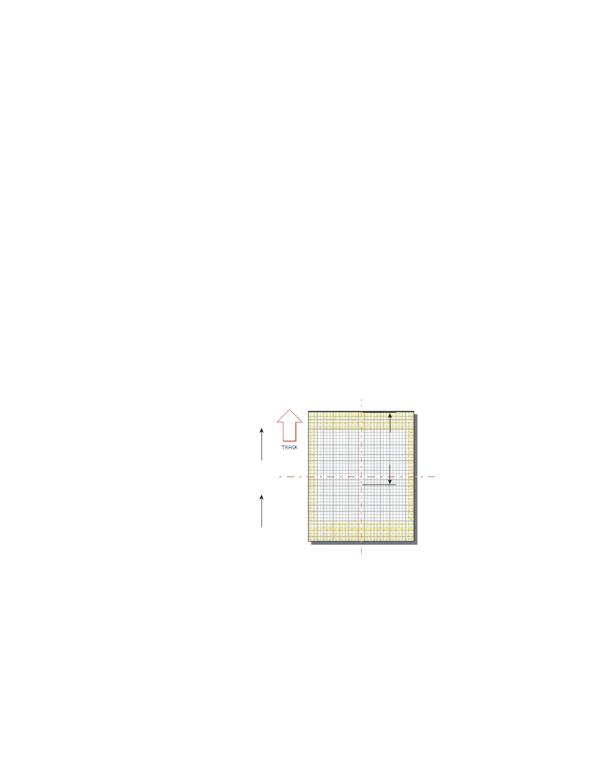
Usable Field Size
Usable Field Size is the distance, in millimeters, from the downstream edge of Mark placement in the
Mark-ing Window to the downstream edge of the Marking Window in the axis of part motion. Figure 5-2
illus-trates Usable Field Size.
Upstream Edge
Downstream Edge
Part
270°
Usable
Field
Size
ABCD1234
Figure 5-2 Usable Field Size