Tracking optimization
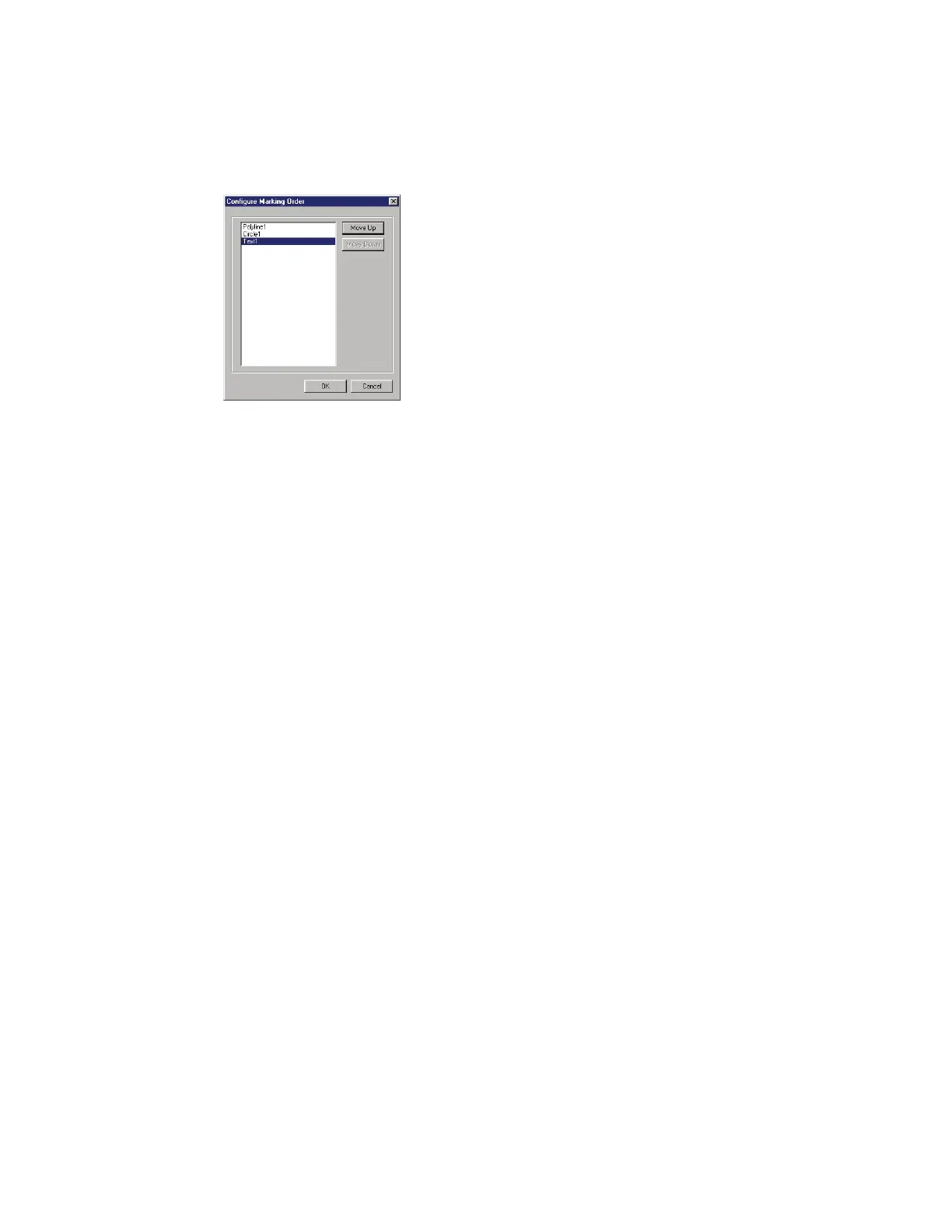
Figure 5-30 Configure Marking Order dialog box
Mark placement
To achieve the highest potential line speed, position the mark near the upstream eld edge of the Marking
Window and then adjust Sensor Distance to position the actual mark on the part.
Note: When positioning objects on the Drawing Canvas, never place any object beyond the edges of the
maximum Marking Window.
Line speed optimization
Tracking variables
There are several variables related to the Tracking Window that can be optimized to increase marking
throughput:
Lengthen Usable Field Size by reducing Mark size.
Rotate the Mark (as shown back in Figures 5-28 and 5-29).
If the Tracking Window is smaller than Usable Field Size, increase the Mark Pitch so that it is equal to,
or
greater than, the Usable Field Size. If this is not possible, then consider adding a second marking head
so that each head marks every other part, which eectively doubles Mark Pitch.
WinMark Pro object property variables
Increase mark Velocity.
Increase Off Vector Velocity.
Reduce Resolution of raster-filled (bitmap) objects.
Use one of WinMark Pro’s built-in stroke fonts instead of TrueType
®
fonts.
If possible, reduce the number of marking characters.
When marking small 2D codes, set the 2D Barcode Bitmap property (located on the Format tab) to
No. This forces WinMark Pro to mark vector circles instead of raster-filling cells.
Simplify line art.
SYNRAD FH Series Flyer Operator’s Manual Version 3.4
114