getting started
32
SYNRAD FH Series Flyer Operator’s Manual Version 3.4
Introduction
The Introduction section includes subsections:
Basic marking setup
FH Flyer features
Control modes
Basic marking setup
The FH Flyer marking head is SYNRAD’s third generation marking product that is evolved from years of
experience with FH Index, Tracker, and Smart heads as well as our SH and DH Series marking heads many
of which are still in use today at customer sites throughout the world. Flyer is capable of marking parts in
stationary applications or can dynamically mark moving parts “on-the-y” at line speeds in excess of 400
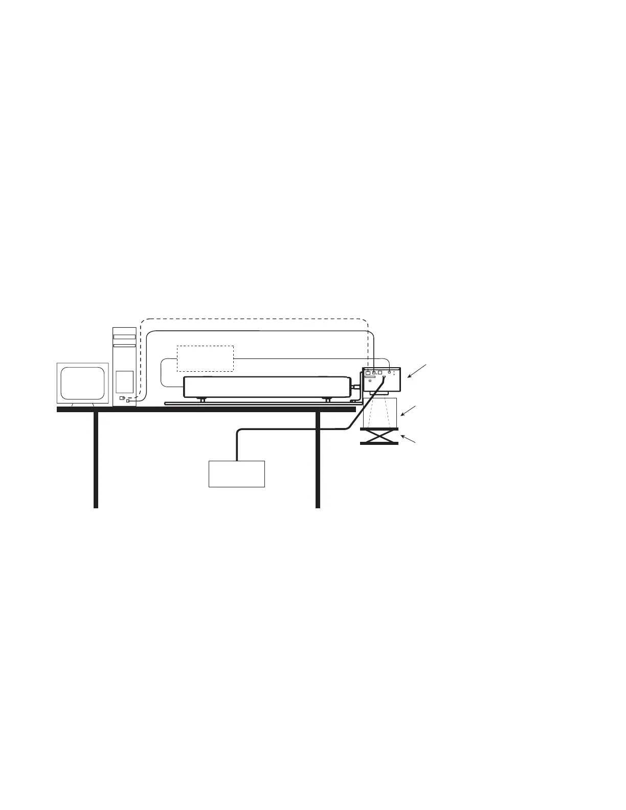
feet per minute. A typical stationary FH Flyer installation is shown in Figure 1-1:
Figure 1-1 Typical FH Flyer static marking setup
The following components shown in Figure 1-1 are available from SYNRAD:
SYNRAD FH Series Flyer marking head w/ SYNRAD CO
2
laser (10 W–125 W)
FLMK mounting kit (Mounting Rail/L-bracket assembly)
30 VDC power supply
SYNRAD’s WinMark Pro v6 Laser Marking Software
You will need to supply the following items to complete the installation:
A computer running Windows
®
7, Vista, XP, or 2000 with two open USB ports
Beam enclosure shield around the work area
A marking surface with an adjustable Z-axis
Adjustable
Marking
Surface
To accurately focus the laser beam
on the marking surface, a Z-axis
adjustment should be provided on
either the marking surface or on the
Beam
Enclosure
Shield
30 VDC
Power Supply
SYNRAD
FH FLYER
Laser Control Cable
10–125W SYNRAD CO
2
Laser
DC Power Cable
RF Power
Supply
(if required)
Ethernet (- - -) or USB (—) Cable