appendix a
230
SYNRAD FH Series Flyer Operator’s Manual Version 3.4
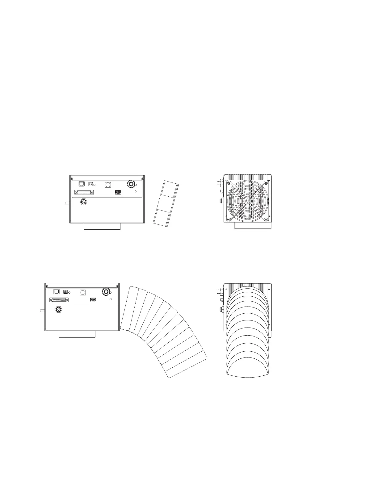
Cold Air Duct From
Cold Air Source
Side View
End View
Cooling
Mounting an auxiliary cooling fan
Use information in this section to mount an external cooling fan or cooling ductwork if you have deter-
mined that additional external cooling is required because (1) Flyer’s heat sink has less than 1.0" (25.4
mm) of free air space between the head and any enclosure or surface, (2) Flyer is oriented such that the
heat sink is pointing downward or in any other non-standard orientation, or (3) Flyer’s calculated internal
maximum temperature is higher than 50 °C.
Tests have shown that adding a cooling fan to provide airow over Flyer’s heat sink can reduce internal
temperatures by 10 °C in demanding marking applications. Choose a cooling fan with an airow rating of
at least 50–100 cubic feet per minute (CFM). For best results, mount the cooling fan or cooling ductwork
at an angle of approximately 15° to the heat sink so that airow is directed slightly upward. The natural
tendency of heat to rise will assist in the heat removal process. See the example drawing in Figure A-2.
Figure A-2 Mounting cooling fan or ductwork to Flyer
Before mounting a cooling fan or ductwork, refer to Figure 5-20 in the Technical Reference chapter for a
diagram showing dimensions
of the four user-accessible mounting holes in Flyer’s heat sink. The mounting
holes are tapped for standard 6–32 UNC screws with a maximum depth of 0.25" (6.35 mm).