getting started
SYNRAD FH Series Flyer Operator’s Manual Version 3.4
39
Mounting
Figure 1-3 Installing the Mounting Rail
L-bracket
Note: Mount your Flyer head to a Flyer (clear anodized) L-bracket. If Flyer is mounted to an existing FH
(black anodized) L-bracket, the center of Flyer’s beam exit is shifted 0.10" (2.54 mm) from the
center of the FH Index/Tracker mark eld in the –X direction (to your right when facing Flyer’s
membrane panel).
The FH Flyer head is positioned by dowel pins on the L-bracket, which in turn is dowel-pinned to the
Mounting Rail. To mount the L-bracket to the Mounting Rail, refer to Figure 1-4 and perform the following
steps:
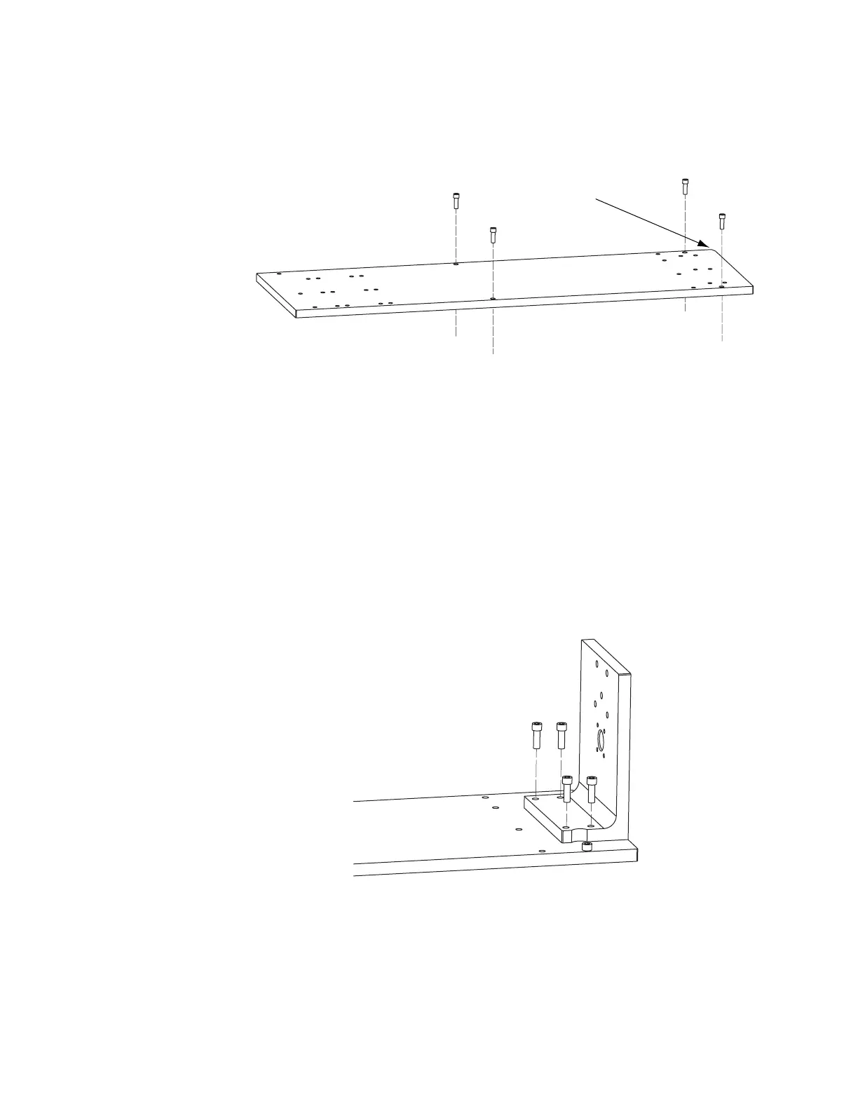
Figure 1-4 Mounting the L-bracket
1
Orient the L-bracket as shown and then place the bracket so that the dowel pins protruding from the
bottom engage the dowel holes in the Mounting Rail.
2
Fasten the L-bracket to the Mounting Rail using four 1/4–20 × 3/4" socket head capscrews.
on left front corner!