SYNRAD FH Series Flyer Operator’s Manual Version 3.4
100
Tracking hardware
Part sensor
When tracking, a part sensor is required to send ‘start mark’ signals to the Flyer marking head on input
IN0 (unless you enable the Internal Part
Trigger property and specify a Part Pitch value). Any number of
capacitive, inductive, photoelectric, or mechanical sensors currently on the market can be used
depending on the part’s material composition and your marking environment. Table 5-2 lists electrical
specifications for choosing a part sensor.
Table 5-2 Part sensor specifications (for IN0)
Function Specications
Input Voltage User determined (+15.0 VDC if powered from Flyer’s internal 15 V supply)
Output Signal Open collector (PNP or NPN) or open drain (P-channel or N-channel)
or debounced mechanical limit switch
Low level output voltage: –1.0 V to +1.0 VDC (0 V typ.)
High level output voltage: +3.0 V to 24.0 VDC
On-state current: 6 mA typical; 9 mA maximum at 5 VDC
16 mA typical; 23 mA maximum at 12 VDC
20 mA typical; 29 mA maximum at 15 VDC
32 mA typical; 47 mA maximum at 24 VDC
Part sensor connection
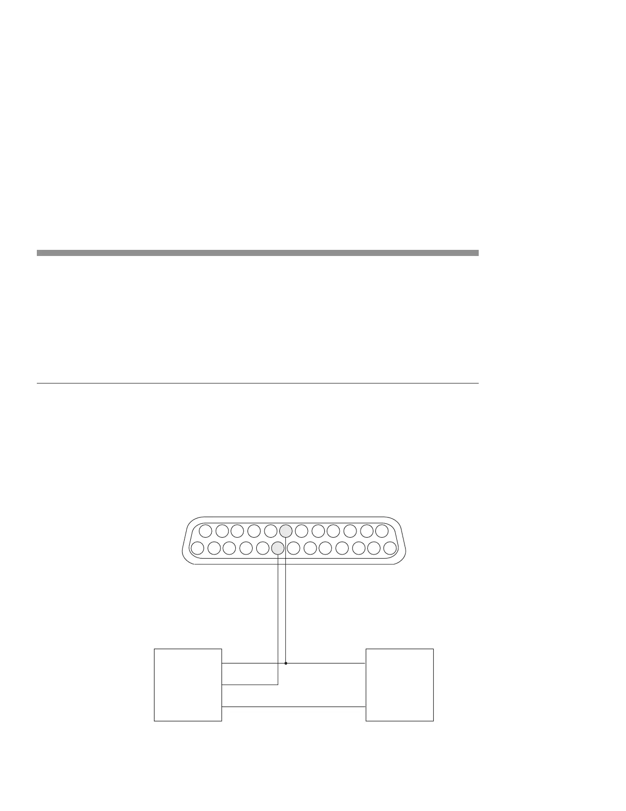
The part sensor output is connected directly to input IN0 on FH Flyer’s User Interface connector. To con-
nect
the part sensor, refer to the appropriate connection diagram. Figure 5-15 shows a customer-
supplied power supply driving a current-sinking NPN open collector part sensor. Figure 5-16 shows how
to power the same type sensor from Flyer’s built-in +15 VDC power supply. See Figure 5-17 and 5-18
when wiring current-sourcing PNP open collector part sensors.
25
24
15
14
13
12
2
1
DC POWER SUPPLYPA RT SENSOR
V+
GND
V+
OUT
GND
8
IN0_A
IN0_B
20
Figure 5-15
Wiring diagram for current-sinking (NPN open collector) part sensors