tracking
SYNRAD FH Series Flyer Operator’s Manual Version 3.4
123
Tracking mark criteria
The entire Target Area of the part, or array of parts, to be marked must move completely within the
Tracking Window before lasing will begin.
Lasing must be completed on the part, or array of parts, before the Target Area of the next part, or
array of parts, reaches the Tracking Window. If lasing is not complete before the Target Area of the
next part reaches the Tracking Window, the next part, or array of parts, is not marked and the mark log
displays a “Line speed too fast to nish - missed start” message. This error means that part sensor sig-
nals are occurring too rapidly because the line speed is moving too fast or parts are spaced too closely
together.
Depending upon Sensor Distance and Mark Pitch, Flyer heads in tracking mode can buer up to 32
‘start mark’ signals. The number of signals buered by the head equals the number of parts that pass
the part sensor before the rst part enters the Tracking Window. Note that when a “Line speed too fast
to nish - missed start” error occurs, the part on which the ‘start mark’ error occurred is not marked.
Marking continues with the next part in the queue.
Encoder Resolution, encoder pulses per millimeter of conveyor motion, must be properly set to
preve
nt mark distortion or marking outside the Target Area. See Tracking hardware later in this chapter
for details on calculating Encoder Resolution. After determining the correct value, open and run
the Linestackxxx.mkh mark le (where xxx matches the focal length of the currently installed lens) to
verify the calculated value. If you are tracking with a Motion Vector other than 270°, you must rotate
the linestack file so that it is oriented properly. When Encoder Resolution is correct, then short and
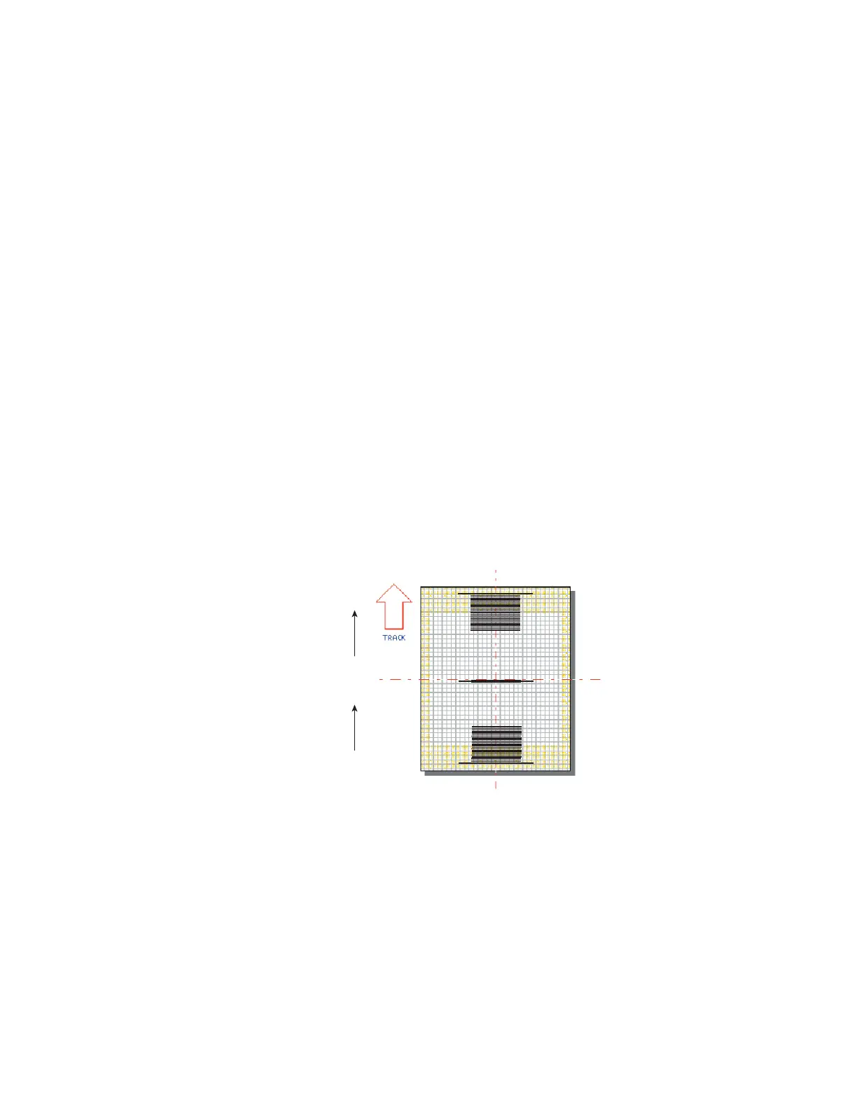
long lines will appear as one long line as shown in Figure 5-7.
Part
270°
MARK CREATED
RESOLUTION IS
TOO LOW
MARK CREATED
RESOLUTION IS
TOO HIGH
MARK CREATED
RESOLUTION IS
CORRECT
Figure 5-7 Checking Encoder Resolution
I
f the long line is further downstream of the short lines in the direction of motion, then increase Encoder
Resolution. If the long line is upstream of the short ones, decrease Encoder Resolution. Accuracy to the
second or third decimal point may be required depending on the resolution of your encoder.
Important Note: If your Flyer system is congured for Encoderless Tracking, the Encoder Resolu-
tion property is not valid. Instead use the Product Line Speed property to ne-tune
tracking to actual part motion.