94
Tracking mark criteria
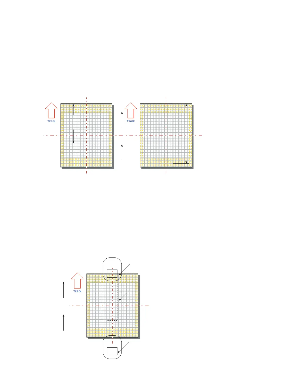
Mark position and orientation make a substantial dierence in tracking speed because they change
Usable Field Size. Maximum line speed is achieved when the Mark is positioned as close as possible
to the upstream edge of the Marking Window. The entire Mark must be positioned on WinMark
Pro’s Drawing Canvas so that it
lies within the boundaries of the Marking Window. Figure 5-8 shows
how the same text positioned differently can give two very different values for Usable Field Size.
Downstream Edge
Part
Motion
270°
Usable
Field
Size
ABCD1234
ABCD1234
Usable
Field
Size
Figure 5-8 Usable Field Size comparisons
When the downstream edge of the Tracking Window coincides with the downstream edge of the Mark-
ing Window, then unmarked portions of the Target Area that move beyond the edge of the Tracking
Window are not marked and lasing stops.
If
part pitch constrains the downstream edge of the Tracking Window within the Marking Window, then
lasing continues until unmarked portions of the Target Area move outside the Marking Window, how-
ever the next part in the queue is not marked. In either case, the mark log displays a “Too fast to fin-
ish” error. In Figure 5-9, “Line 2” will mark unless unmarked areas move outside the Marking Window.
Figure
5-9 Maximum marking position in Tracking Window
SYNRAD FH Series Flyer Operator’s Manual Version 3.4
Part
270°
Line 1
Line 2
Line 1
Line 2
Target Area on Part
Tracking Window
Line 2 must finish marking
before any unmarked por
exit the Tracking Window