getting started
40
SYNRAD FH Series Flyer Operator’s Manual Version 3.4
Mounting
FH Flyer marking head
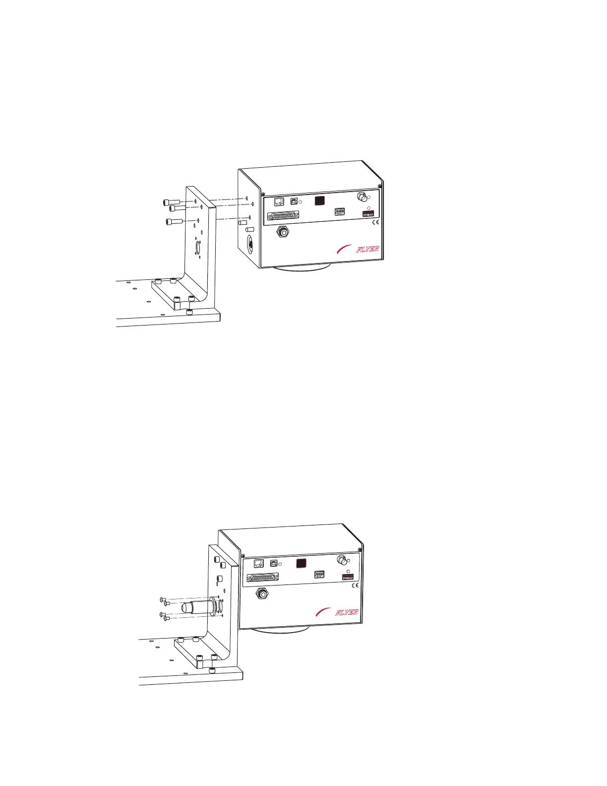
To mount your FH Flyer marking head to the L-bracket, refer to Figure 1-5 and perform the following steps:
Figure 1-5 Mounting the Flyer head
1
Remove the telescope optics cover from the rear (beam input end) of the Flyer head.
2
Place the FH Flyer marking head on the L-bracket so that the dowel pins protruding from the rear of
the head engage the dowel holes in the L-bracket.
3
Install and tighten three 1/4–20 × 3/4" socket head capscrews through the L-bracket into the Flyer
head.
4
Fasten the Beam Enclosure Tube to the L-bracket using four 8–32 × 1/4" button head socket screws
as shown in Figure 1-6. Tighten the screws just enough to hold the Beam Enclosure Tube in position;
this allows the tube some exibility to align with the bevel on the laser faceplate in the next step.
Figure 1-6 Installing the Beam Enclosure Tube
ETHERNET
USB
LASER
CONTROL
POWER
USER INTERFACE
TEST
MARK
STATUS
PWR
FH
MARKING HEAD
FLYER
ETHER
NET
USB
LAS
ER
CON
TROL
POWER
USE
R INTE
RFA
CE
TEST
MARK
STATUS
PWR
FH
MARKING HEAD
FLYER