getting started
44
SYNRAD FH Series Flyer Operator’s Manual Version 3.4
Connecting
4
Attach the DC Power cable’s red wire to the positive (+) terminal on the +30 VDC power supply.
5
Attach the power cable’s black wire to the negative (–) terminal on the DC supply.
6
Attach the power cable’s green wire to earth ground.
Caution
possible
equipment
damage
FH Flyer marking heads require a DC power supply voltage of +30.0
VDC ± 2.0 V. The Flyer head may not function properly if the DC
supply voltage drops below +28.0 VDC. Before connecting the DC
Power cable, measure your DC supply’s output voltage under load to
ensure that it can provide +30 VDC.
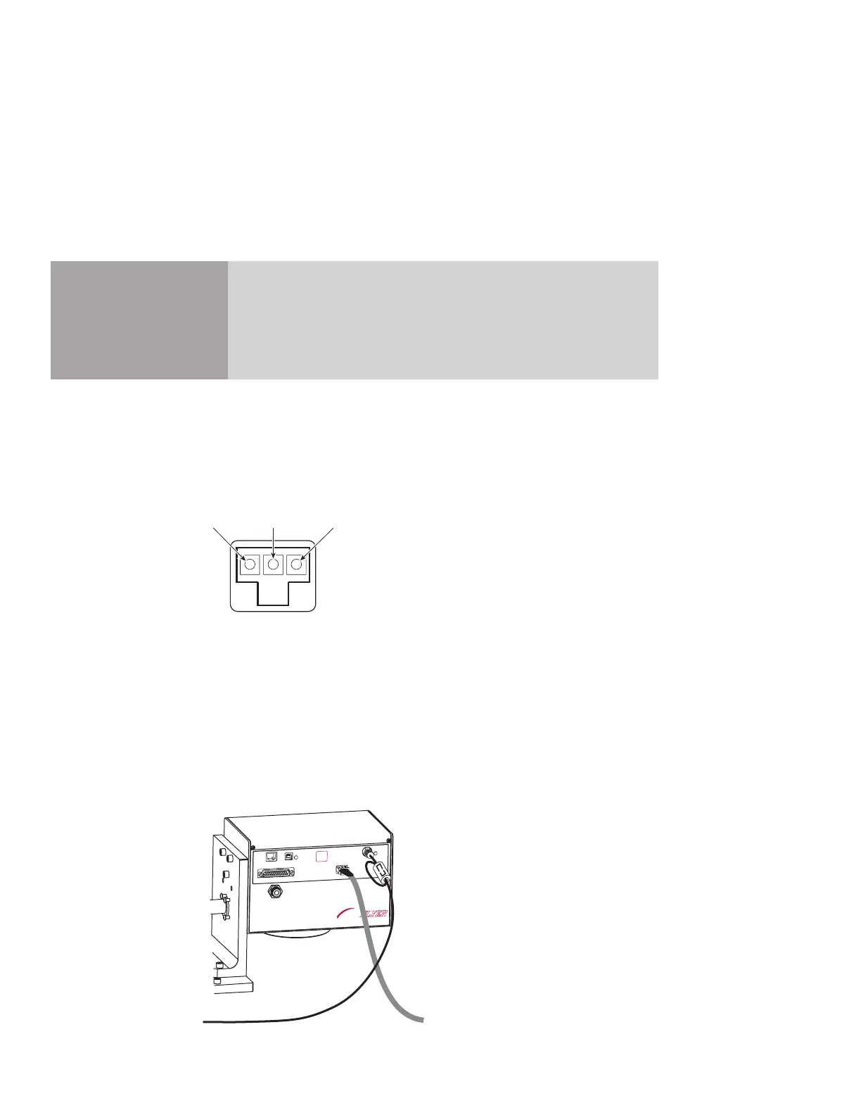
Note: If you require a custom length DC Power cable, a spare power connector with crimp pins for
18–24 AWG wire is included in the Accessory Kit. When wiring the spare connector, refer to
Figure 1-9 below for the polarity of Flyer’s Power jack (as seen when facing the Flyer head).
Figure 1-9 Polarity of Flyer’s Power jack
Laser Control cable
Locate the Laser Control cable in the ship kit. It is a 6 foot (1.8 m) long coaxial cable with male BNC
connectors on each end. To aid electrical noise suppression, one end of the Laser Control cable is looped
through a ferrite bead. Connect this end of the cable to the Flyer head (see Figure 1-10). Install the Laser
Control cable between Flyer and your laser according to the laser types listed below.
FH
MARKING HEAD
FLYER
ETHERNET
USB
LASER
CONTROL
POWER
USER INTERFACE
TEST
MARK
STATUS
POWER
(+)
(Ground)
(-)
Figure 1-10 Connecting the Laser Control cable