maintenance/
troubleshooting
SYNRAD FH Series Flyer Operator’s Manual Version 3.4
221
Troubleshooting
Review the Input/output circuitry section in the Technical Reference chapter to verify that I/O signals are
in the correct voltage range of 5 V to 24 VDC. Use a voltmeter to measure your I/O signals while they are
connected to Flyer’s DB-25 User Interface connector.
Note: Flyer’s input/output voltage range is dierent from previous FH heads (Index/Tracker/Smart)
where the allowable voltage range was 15 V–40 VDC. Flyer I/O voltages must be in the range of
5 V–24 VDC.
I/O wiring is not properly connected to the marking head.
Double-check eld wiring to ensure that input/output signals are routed to the correct pins on the User
Interface connector and that their respective return (ground) paths are wired to the proper pins. Refer to
Input/output circuitry in the Technical Reference chapter for information about connecting signals to/from
Flyer. This section also contains information about converting an existing FH Index or Tracker system for
Flyer-compatibility.
Important Note:
Flyer’s DB-25 User Interface connector pinout does not match the pinout on the FH
Smart DB-25 Parts Handling Control connector.
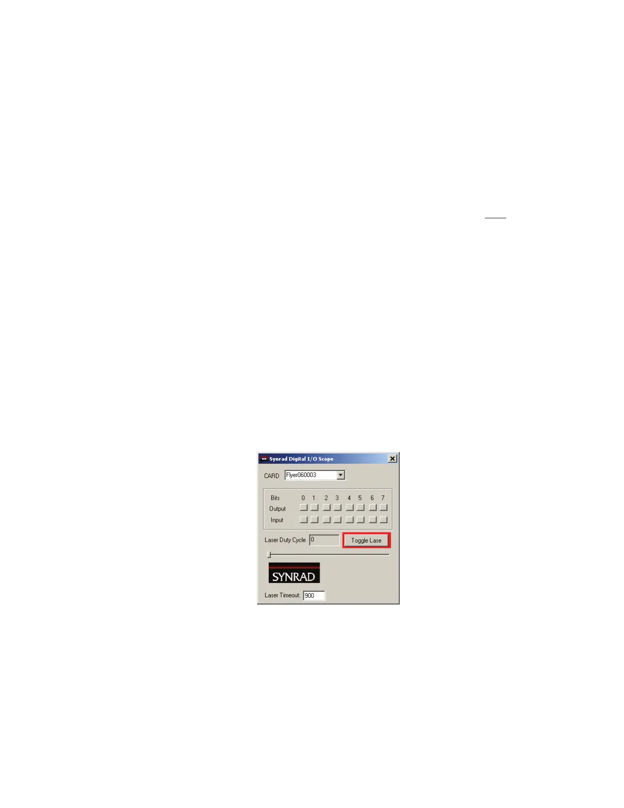
Use Digital Scope (DigScope.exe), shown in Figure 7-4, to verify proper I/O functionality between FH
Flyer and the automation controller. Digital Scope’
s input “buttons” pop-in as an input is activated (when
the correct voltage level is applied). Press an output “button” to activate an output.
Figure 7-4
Digital Scope window
Laser Marking FAQ
Our Laser Marking FAQ, available for downloading or browsing from the WinMark Pro web site at http://
www.winmark.com, answers many common marking questions in categories including General troubleshoot-
ing, WinMark Pro automation, Tracking operation, ActiveX, and others. The Laser Marking FAQ also includes
links to various SYNRAD technical bulletins.