operation
70
SYNRAD FH Series Flyer Operator’s Manual Version 3.4
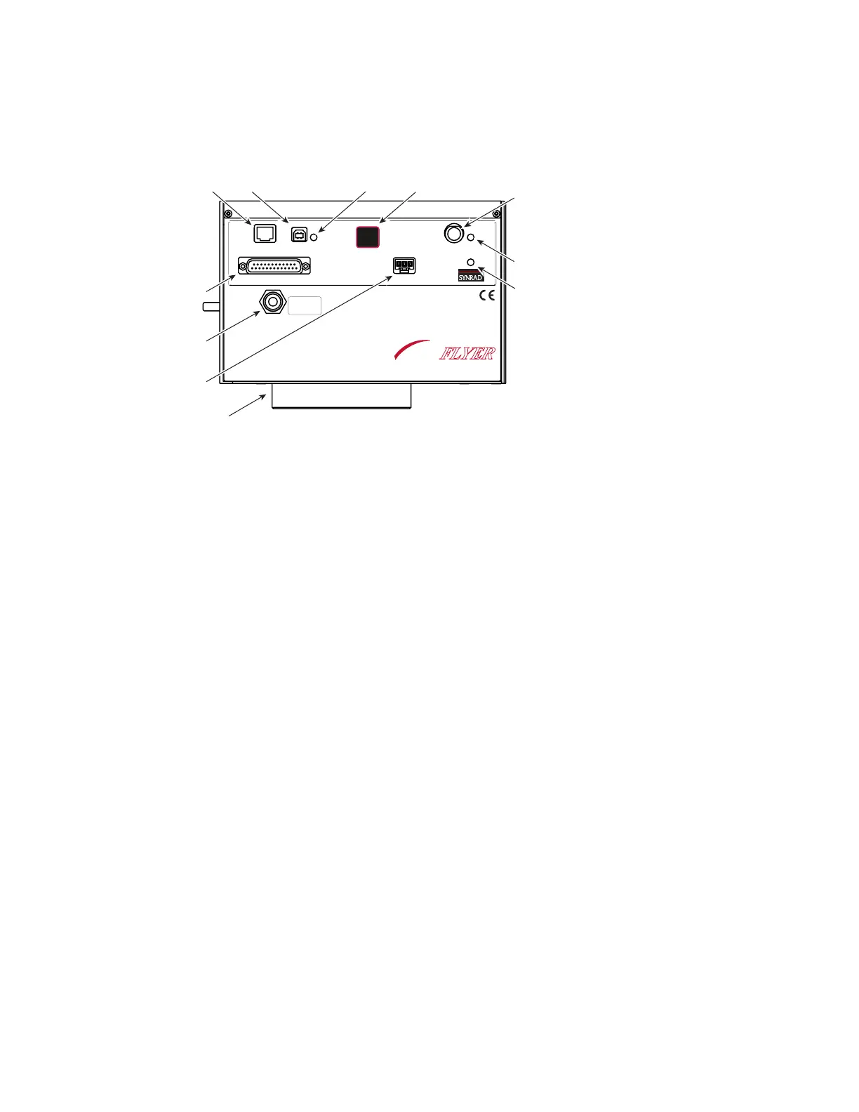
Controls and indicators
Figure 3-1 FH Flyer control panel
1
Pwr Indicator – illuminates green when +30 VDC is applied to Flyer.
2
Status Indicator – ashes green during normal boot-up, turning to solid green when Flyer is fully
operational. The Status indicator ashes green at a faster rate during marking operations. Certain
conditions cause the Status indicator to ash various green or red sequences. Refer to Troubleshooting
in the Maintenance/Troubleshooting chapter for a table showing various indicator states.
3
Laser Control Connector – sends tickle and PWM Command signals to the laser.
4
Test Mark Pushbutton – marks a factory-installed test pattern (see Figure 2-3) using approximately
50% of the laser’s rated output power at a marking velocity of 40 inches per second. The Test Mark
button also res any Custom Test Mark les loaded into memory and can reset stand-alone operation
(see the Stand-alone Operation chapter for details).
5
USB Indicator – illuminates green when the FH Flyer and the computer are both powered up and
connected via the USB Communication cable. The USB LED turns red when WinMark Pro is com-
municating with Flyer.
6
USB Port – provides a connection point for a USB interface between your computer and the Flyer
head.
7
Ethernet Port – provides a connection point for an Ethernet network interface between your com-
puter, server, or network and the Flyer head.
8
User Interface Connection – provides a male DB-25 connection to Flyer’s eight inputs, eight outputs,
and an isolated 15 VDC, 400 mA I/O power supply.
9
Gas Purge Port – provides a connection point for a customer-supplied purge gas. A low-pressure (2–5
PSI) gas purge creates a slight positive pressure inside the head, which lowers the risk of contamina-
tion of internal optical surfaces.
10
Power Connector – receives 30 VDC @ 4 Amps maximum from the DC power supply through the
DC Power cable.
11
Focusing Lens – focuses the laser beam onto the marking surface. Each lens has a nominal working
distance engraved on the bottom face of the lens mount. Refer to the Final Test Report shipped with
your Flyer head for the actual measured working distance.
ETHERNET
USB
LASER
CONTROL
POWER
USER INTERFACE
TEST
MARK
STATUS
PWR
8
9
FH
MARKING HEAD
FLYER
GAS PURGE
CLEAN AND DRY AIR
OR NITROGEN ONLY
2-5 PSI