technical reference
SYNRAD FH Series Flyer Operator’s Manual Version 3.4
145
Name RJ45 Pin # Cable Color RJ45 Pin # Name
TX+ 1 White/Orange 3 RX+
TX– 2 Orange 6 RX–
RX+ 3 White/Green 1 TX+
n/c 4 Blue 4 n/c
n/c 5 White/Blue 5 n/c
RX– 6 Green 2 TX–
n/c 7 White/Brown 7 n/c
n/c 8 Brown 8 n/c
n/c — not connected
Figure 6-13 shows the physical wiring for crossover Ethernet cable.
TEST
MARK
POWER
LASER
CONTROL
STATUS
PWR
USB
USER INTERFACE
ETHERNET
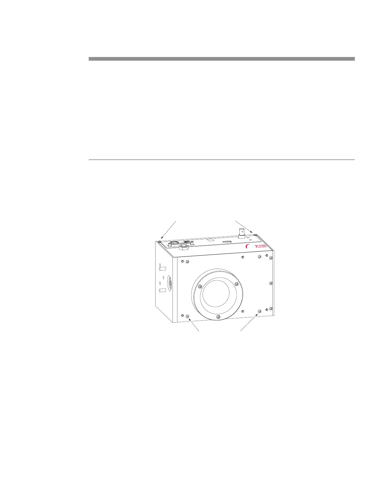
Remove two button head screws
Remove two capscrews
FH
MARKING HEAD
FLYER
Figure 6-13 Physical wiring—crossover Ethernet connection
Fast Acting Safety Interlock
Many marking applications require a safety action to occur for each part that is marked. An example of
this action is a machine that lowers a shield over a part prior to marking, and then raises the shield to
advance the part as soon as the mark is complete. SYNRAD lasers are equipped with a Remote Interlock
feature that disables laser ring, typically when a safety switch on an access door or enclosure is opened.
However in marking applications where a safety interlock is frequently cycled, the Remote Interlock may
create an unacceptable delay. This delay occurs because closing the interlock (and cycling the Keyswitch,
or remote keyswitch, on Keyswitch-equipped lasers) invokes a built-in ve-second delay prior to lasing.