SYNRAD FH Series Flyer Operator’s Manual Version 3.4
146
LASER
ROL
STATUS
1
2
3
4
1
2
3
4
SW1
SW2
Move switch 1 on switch bank SW1
to the “ON” position to enable FASI
SW1
SW2
1
2
3
4
1
2
3
4
ON – OFF
ON – OFF
To address this issue, FH Flyer marking heads incorporate a Fast Acting Safety Interlock (FASI) function.
The FASI function prevents Flyer from generating a PWM Command signal unless an active input is pres-
ent on input IN3. When an enable signal is applied, FH Flyer responds to the rising edge transition in less
than 1 millisecond (ms).
Important Note: The Fast Acting Safety Interlock (FASI) function does NOT disable the laser. FASI
only prevents FH Flyer from sending PWM Command signals to the laser. Flyer still
sends tickle pulses (1 µs @ 5 kHz) out the Laser Control port in order to maintain
plasma ionization inside the laser.
To enable Flyer’s FASI feature, refer to Figure 6-14 and perform the following steps:
Figure 6-14 Opening Flyer to enable FASI
1
Remove DC power from the Flyer head or disconnect the DC Power cable.
2
Refer to Figure 6-14 and withdraw two button head Allen screws and two Allen head capscrews
at the locations shown to remove Flyer’s upper cover.
3
Ground yourself by keeping one hand in constant contact with Flyer’s lower metal cover.
4
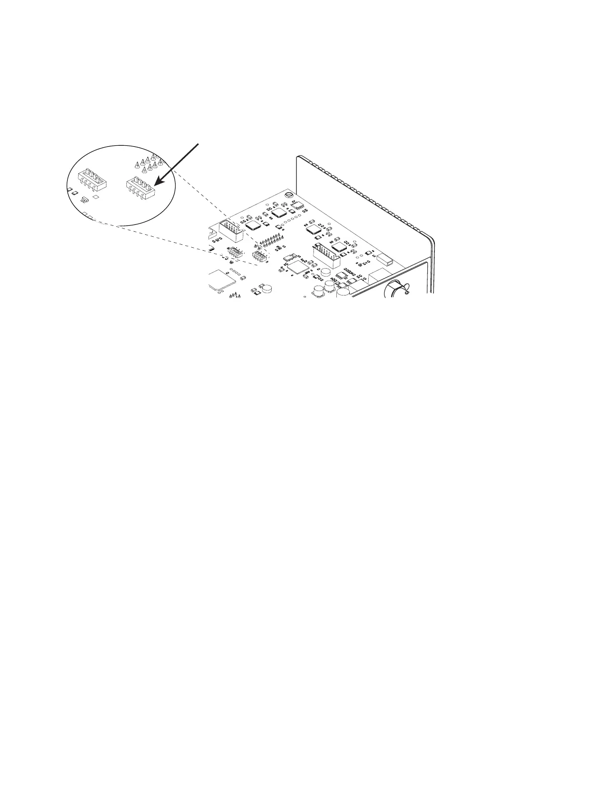
Locate the DIP switch bank labeled SW1 on the CPU board (see Figure 6-15) and move switch #
1 to the “ON” position.
Fast Acting Safety Interlock
Figure 6-15 Flyer DIP switch locations
5
All other switches must remain at their default settings as listed on Table 5-21 below.
6
Replace Flyer’s upper cover and tighten the screws removed in Step 2.
7
Open your mark les and congure WinMark’s Wait Digital Before Piece automation command to
wait for a “Set” state on input IN3 before marking begins. This step synchronizes marking operations
with the FASI safety feature.
8
To begin lasing with FASI enabled, apply a 5–24 VDC signal to Flyer input IN3.