operation
SYNRAD FH Series Flyer Operator’s Manual Version 3.4
71
Initial start-up
The Initial start-up section includes subsections:
Test ring the laser
Marking in WinMark control mode
Test ring the laser
To test the setup of your FH Series Flyer marking head and laser after completing the connections de-
scribed in the Getting Started chapter, perform the following steps:
1
Remove the red dust cap from Flyer’s focusing lens.
2
Place the material to be marked (a sheet of anodized aluminum is ideal) on your marking surface in
the eld of the focusing lens.
3
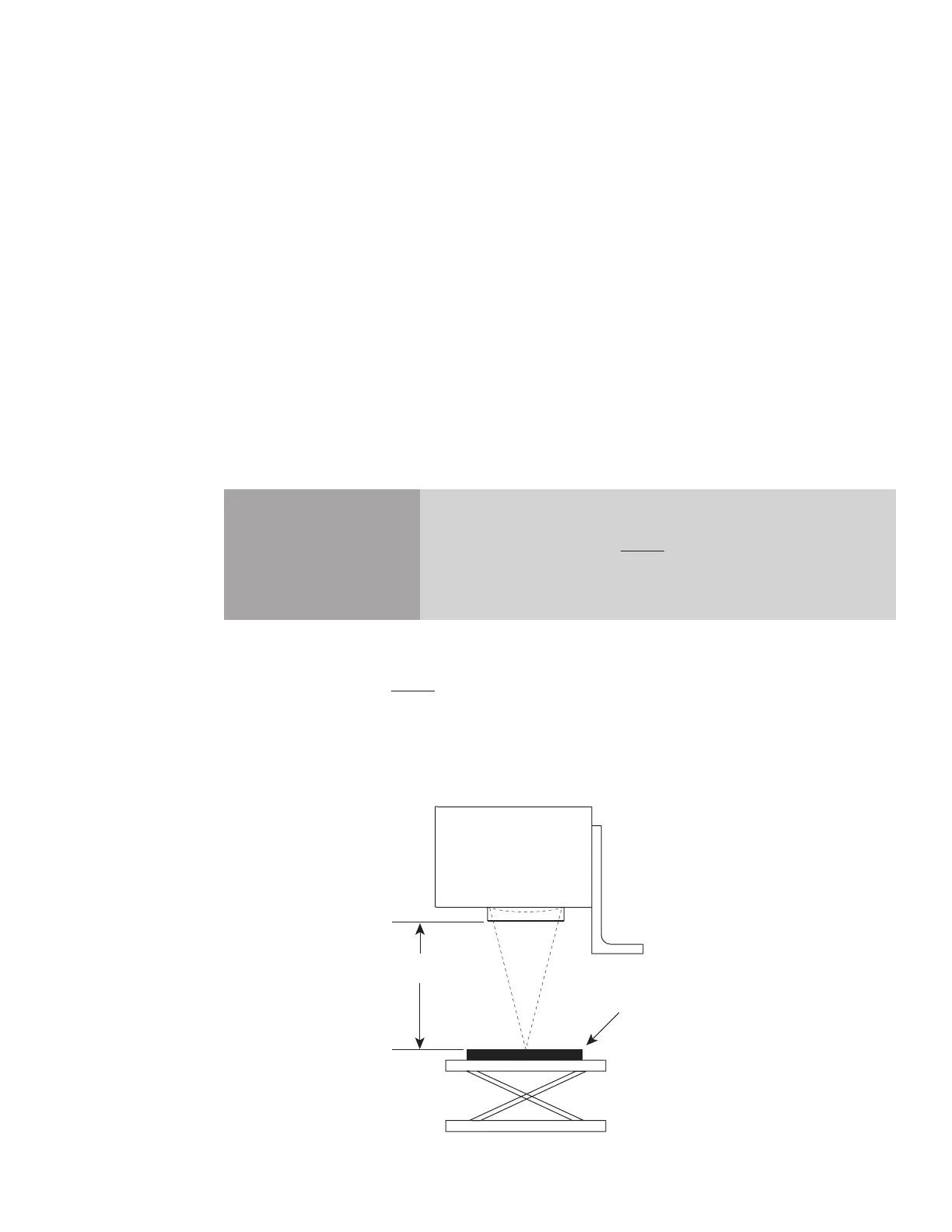
Use a ruler marked in millimeters to set the working distance (Z-axis adjustment) from the bottom
of the focusing lens mount to the mark surface as shown in Figure 3-2. The nominal working dis-
tance is engraved on the bottom of the focusing lens mount. Because working distance is unique to
each individual lens, consult the Final Test Report shipped with your FH Flyer head to determine
the actual working distance of your lens. Refer to Table 6-1 in the Technical Reference chapter for
FH Series focusing lens specifications.
Caution
possible
equipment
damage
Lens damage may occur if the measuring device contacts the surface
of the focusing lens. Always measure the working distance from the
bottom of the focusing lens mount.
Figure 3-2 Working distance measurement
W
Working
Distance