technical reference
SYNRAD FH Series Flyer Operator’s Manual Version 3.4
143
(1)
(2)
(1) TX +
(2) TX –
(3)
(6)
(3) RX
(6) RX –
n/c (4)
n/c (5)
(4) n/c
(5) n/c
n/c (7)
n/c (8)
(7) n/c
(8) n/c
WHT/ORG
ORG
WHT/GRN
GRN
BLUE
WHT/BLUE
WHT/BRN
BRN
Ethernet/Flyer cabling
In most cases, you can purchase an Ethernet patch cable or crossover cable in the correct length for
your application. The type of computer network used in your facility will determine which type of cable
is required—if in doubt contact your company’s Network Administrator. If you require a longer cable
than is commercially available or prefer to build your own custom length cable, then refer to the Tables
and Fig-ures below. Table 6
-19 and Figure 6-12 provide details for a straight-thru Ethernet cable while
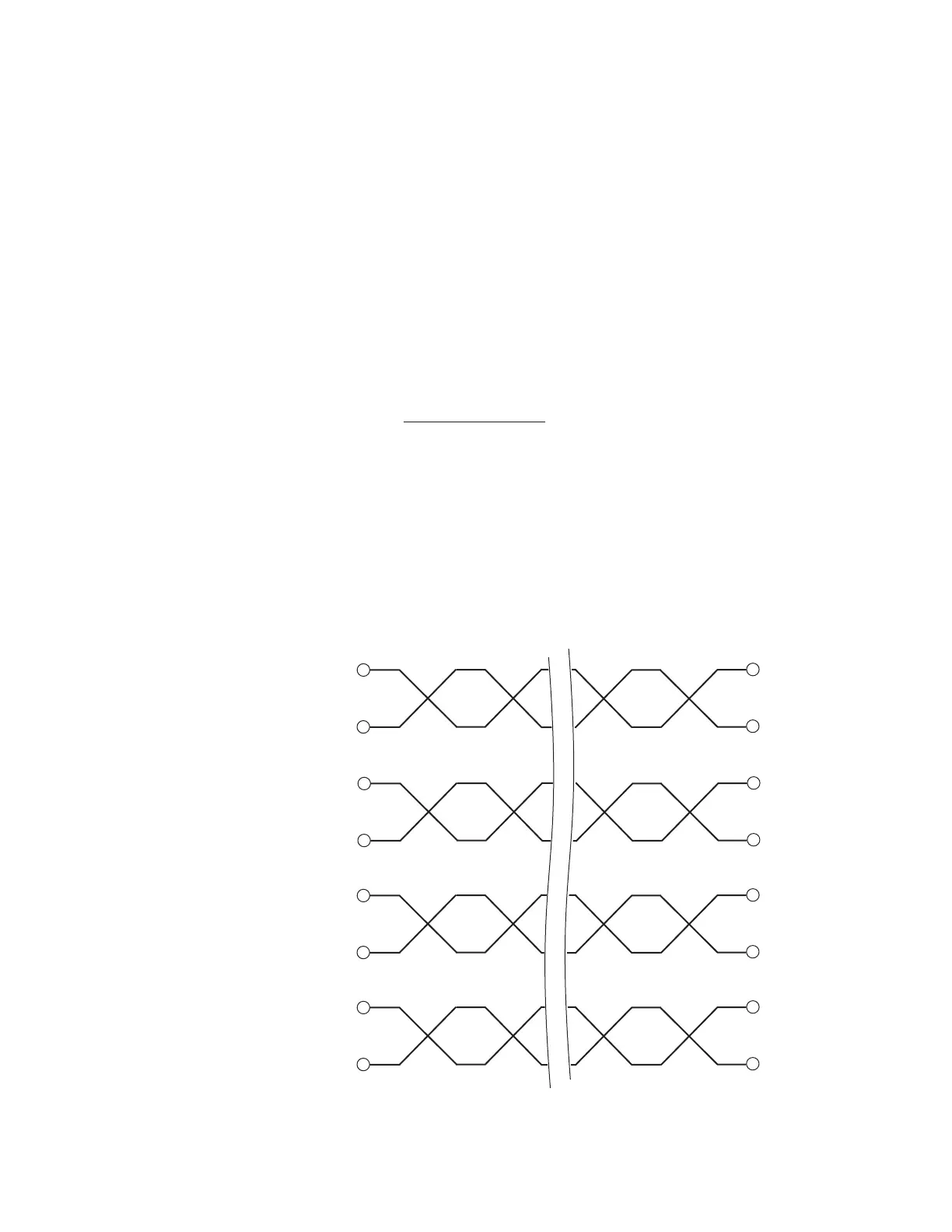
Table 6-20 and Figure 6-13 describe a crossover Ethernet cable.
Ethernet wiring notes
Use male RJ45 connectors on both ends of the Ethernet cable.
Use Category 5 (CAT5 or CAT5e) Ethernet cable.
Each twisted cable pair must be kept as a pair. TX+ / TX– must be a pair; RX+ / RX– must be another
pair; etc.
Pair 1 (the blue pair) connects to pins 4 & 5; pair 2 (orange pair) connects to pins 1 & 2; pair 3
(green pair) connects to pins 3 & 6; and pair 4 (brown pair) connects to pins 7 & 8.
Color codes are referenced to the pin numbers and names on the host interface.
Ethernet port
Table 6-19 provides pin assignments for straight-thru Ethernet cable.
T
able 6-19 Ethernet pin assignments—straight-thru connection