SYNRAD FH Series Flyer Operator’s Manual Version 3.4
144
Name RJ45 Pin # Cable Color RJ45 Pin # Name
TX+ 1 White/Orange 1 TX+
TX– 2 Orange 2 TX–
RX+ 3 White/Green 3 RX+
n/c 4 Blue 4 n/c
n/c 5 White/Blue 5 n/c
RX– 6 Green 6 RX–
n/c 7 White/Brown 7 n/c
n/c 8 Brown 8 n/c
n/c — not connected
Figure 6-12 shows the physical wiring for a straight-thru Ethernet cable.
Figure 6-12 Physical wiring—straight-thru Ethernet connection
Ethernet port
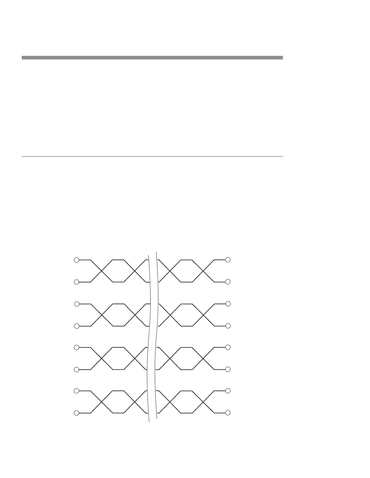
Table 6-20 provides pin assignments for wiring a crossover Ethernet
cable.
Table 6-20 Ethernet pin assignments—crossover connection
(1)
(2)
(3) RX
(6) RX
(3)
– (6)
(1) TX
(2) TX –
n/c (4)
n/c (5)
(4) n/c
(5) n/c
n/c (7)
n/c (8)
(7) n/c
(8) n/c
WHT/ORG
ORG
WHT/GRN
GRN
BLUE
WHT/BLUE
WHT/BRN
BRN