Determining line speed
The Determining line speed section includes subsections:
Line speed formula
Sample calculations
Line speed formula
Note: Line speed calculations do not account for the time required for automation processes to complete
their respective tasks between marks. These factors must be considered when determining the
actual throughput of your production line. As with any factory automation proposal, proof-of-
concept testing is highly recommended. The rst step in achieving maximum line speed is to opti-
mize your mark le to meet mark speed and mark quality requirements for the specic material to
be marked.
The formula described below provides the approximate maximum line speed for a specic mark le using
an FH Series Flyer marking head in tracking mode.
Line Speed = Tracking Window / Cycle Time
Sample calculations
Sample calcu
lation #1 and Sample calculation #2 guide you through the denitions described earlier so that
the correct values for tracking parameters can be determined and inserted into the line speed equation.
Sample calculation #1
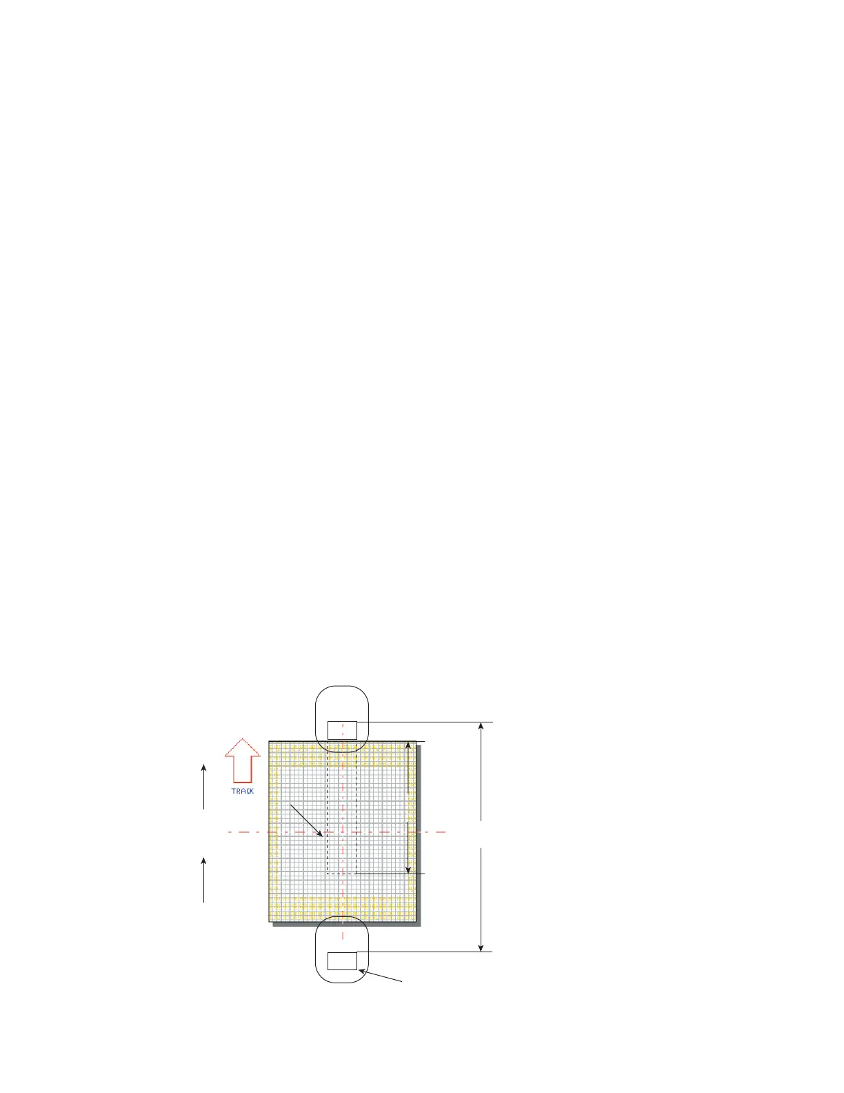
Refer to Figure 5-26 and read through the following sample line speed calculation.
Figure 5-26
Tracker line speed calculation #1
SYNRAD FH Series Flyer Operator’s Manual Version 3.4
110
Part
270°
S/N063
101602
Tracking
Window
S/N063
101602
Usable Field Size
152 mm
Mark Pitc
180 mm