tracking
SYNRAD FH Series Flyer Operator’s Manual Version 3.4
111
Determining line speed
The mark is being made by a Flyer head in tracking mode using a 200 mm FH lens; maximum lens eld
dimensions are 165 mm × 134 mm. A Motion Vector of 270° is set due to the application’s part motion
requirements. Mark placement in the Marking Window is such that the Usable Field Size is 152 mm.
The Tracking Window is dened as the smaller of either Usable Field Size or Mark Pitch. Usable Field Size is
152 mm and Mark Pitch is 180 mm, so the Tracking Window is 152 mm.
Cycle Time for the mark (optimized in static marking mode) is 0.32 seconds.
Line Speed = Tracking Window / Cycle Time
= 152 mm / 0.32 sec
Line Speed = 475 mm/sec = 28.5 m/min = 93.5 ft/min
Sample calculation #2
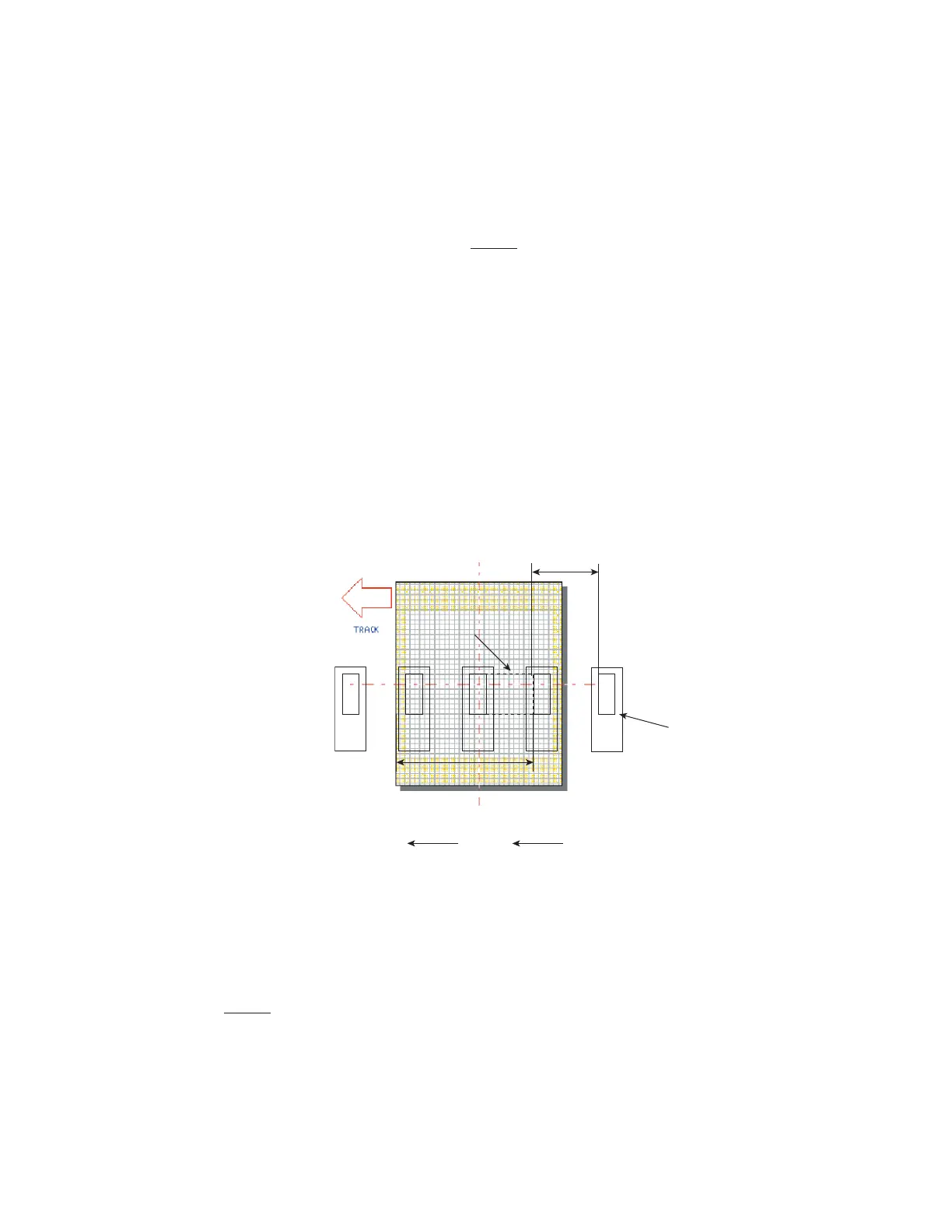
Refer to Figure 5-27 and the following sample line speed
calculation.
Figure 5-27 Tracker line speed calculation #2
The mark is being made by a Flyer head in tracking mode using a 125 mm FH lens. Maximum lens eld
dimensions are 105.6 mm × 85.7 mm. A Motion Vector of 180° is set due to the application’s part mo-
tion requirements. Usable Field Size is 68 mm and Mark Pitch measures 30 mm. The Tracking Window, the
smaller of either Usable Field Size or Mark Pitch equals 30 mm.
Cycle Time for the mark is 0.20 seconds.
Line Speed = Tracking Window / Cycle Time
= 30 mm / 0.20 sec
Line Speed = 150 mm/sec = 9 m/min = 29.5 ft/min
Part
Motion
Target Area on Part
Tracking
Window
Usable Field Size
68 mm
30 mm
123456
123456
123456
123456