WinMark Pro tracking setup
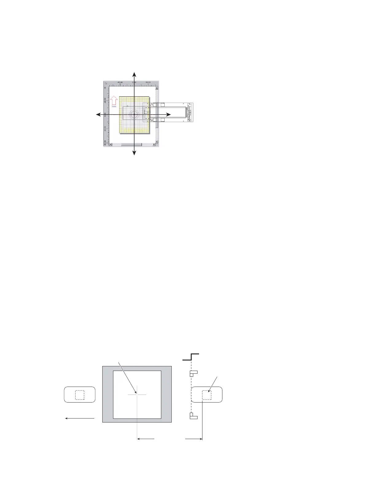
Figure 5-21
Drawing Canvas coordinates relative to FH Flyer
Sensor Distance
The term Sensor Distance is not entirely accurate because the value entered is not related to the physical
part sensor location, but rather Sensor Distance is dened as the distance, at the moment of part sense,
from the centerline of the Marking Window to the leading edge of the desired mark location on the
part. Unlike other marking systems that are time-based, FH Flyer uses a distance-based marking scheme.
This is because at the moment a part is sensed (on the rising or falling edge of the part sense signal), FH
Flyer begins counting encoder pulses. Marking begins when the number of encoder pulses counted by the
head equals the Sensor Distance minus the distance from the center of the Marking Window to the Object
Reference Point. Because FH Flyer calculates marking vectors based on encoder pulses (distance), Flyer’s
tracking algorithm can continue to accurately mark an object even when it stops or reverses direction,
once the Target Area has fully entered the Tracking Window.
Change Sensor Distance to move the location of the mark on the part in the axis of part motion. Moving
the location of the mark object on WinMark Pro’s Drawing Canvas (in the axis of part motion) has no
affect on part mark position. Figure 5-22 illustrates the Sensor Distance concept. In this case, the part
sensor is placed upstream of the mark eld (parts are sensed before they reach the center of the mark eld)
and the sensor is set to trigger on a rising edge transition.
90°
0°
PART MOTION COORDINATE SYSTEM OF WINMARK
DRAWING CANVAS RELATIVE TO FH FLYER / LASER
Center of Mark Field
Part Motion
(270°)
ABC
1234
ABC
1234
Sensor Distance
(at moment of part sense)
Part 1
Part 2
(Target Area)
Part Sense
Figure
5-22 Upstream part sensor, rising edge trigger
SYNRAD FH Series Flyer Operator’s Manual Version 3.4
106